
News center
Related Posts
Online Message
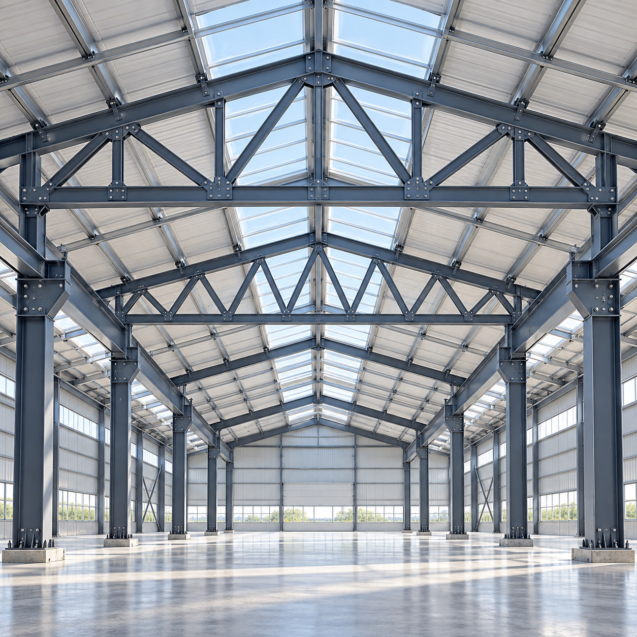
A Steel Truss Structure is not chosen simply by span length. The right system depends on how loads enter the building, how much clear space is needed below the roof, whether services must pass through the structure, how the building will be erected, and whether future expansion is likely. Two trusses can cover a similar width yet perform very differently when exposed to crane loads, heavy snow, wind uplift, suspended equipment, or an irregular building layout.
For early comparison, it helps to separate conventional plane trusses from larger structural systems. Pratt, Warren, Howe, and Fink trusses are usually individual roof trusses repeated along a building. Portal trusses and space frames are broader systems that solve different problems: portal trusses combine trussed rafters with rigid frames, while space frames distribute loads in three dimensions. None is universally “best.” Each works well when its geometry matches the building’s real loading and use.
How a Steel Truss Carries Load
A truss is a triangulated framework. Ideally, its members mainly resist axial force: tension or compression. This is materially efficient because a member acting mainly in tension or compression can often be lighter than a solid beam resisting the same load through bending. The top chord commonly carries compression under gravity loads, while the bottom chord commonly carries tension. Diagonal and vertical web members transfer forces between them.
That simple description has an important practical limit: the members, connections, and bracing must all work together. Compression members can buckle if they are too slender or insufficiently restrained. Connections must transfer the intended forces without creating weak points. Roof purlins, longitudinal bracing, wall bracing, and the supporting columns are therefore part of the structural solution, not secondary details added after the truss is selected.
A truss also has depth. Increasing depth generally improves structural efficiency because the chords are farther apart, reducing their force for a given bending demand. The trade-off is that a deeper truss occupies more vertical space. In a warehouse, that may reduce usable clear height; in an arena or terminal, it may interfere with mechanical services, lighting, or architectural sightlines.
Common Steel Truss Types and Their Best Uses
Pratt trusses: a practical industrial roof choice
The Pratt truss uses vertical members and diagonals that usually slope toward the center of the span. Under typical downward roof loading, the long diagonals tend to act in tension. Tension members can be relatively slender and economical, which is one reason Pratt geometry is common in steel roof trusses.
It performs particularly well in regular buildings where roof loads arrive at predictable panel points. A factory, workshop, or storage building with repeated bays and conventional purlin spacing is a natural fit. It becomes less straightforward when equipment loads are hung between panel points, when large roof penetrations interrupt the web pattern, or when uplift loading is significant. These conditions do not rule out a Pratt truss, but they require the force pattern to be checked for more than one load direction.
Warren trusses: useful when a regular pattern matters
A Warren truss is recognized by its repeated triangular web arrangement. It often has fewer member types than a truss with verticals, which can simplify fabrication and produce a clean visual rhythm. Its triangular panels also make it adaptable when roof loads are distributed fairly evenly.
This system is often a sensible option for long, repetitive roof structures, pedestrian canopies, and other applications where members can align naturally with roof support points. The layout needs more thought when there are concentrated loads. A heavy rooftop unit or a hanger load should ideally be introduced at a panel point. Adding a concentrated load between nodes can force local bending into members that were intended to act primarily in axial force.
Howe and Fink trusses: not interchangeable alternatives
The Howe truss reverses the usual diagonal direction seen in a Pratt truss. Under gravity loading, the diagonals commonly take compression. That is not inherently wrong, but it changes the design emphasis. Steel compression members need adequate section shape, restraint, and connection detailing to avoid buckling. A Howe arrangement may suit a particular geometry, but it should not be selected simply because its pattern looks familiar.
Fink trusses are most associated with pitched roofs. Their internal W-shaped web arrangement divides the roof into shorter panels and can work efficiently in a repeated roof module. They are generally better suited to straightforward roof loading than to buildings with extensive services, large openings, or heavy suspended plant. If ductwork, fire mains, conveyors, and cable trays need to cross the roof zone, the apparent material saving of a dense web layout can be offset by coordination difficulties.
When Portal Trusses Make More Sense Than Repeated Roof Trusses
A portal truss is a useful hybrid where a building needs the clear span associated with portal framing but a trussed rafter is preferable to a solid web member. The columns and rafters form rigid frames, while the rafter itself uses a truss configuration. This can be a practical approach for broad industrial buildings, hangars, and facilities where interior columns would disrupt production flow, vehicle movement, or storage layout.
The benefit is not only span. The frame can create a clear central volume while keeping the primary structure organized at the building perimeter. However, portal action shifts attention to the eaves, column bases, and foundations. These locations carry substantial force and must be coordinated with the foundation concept early. A roof truss cannot be assessed in isolation from its supports.
Portal trusses are also worth considering when future internal changes are likely. A building designed around clear spans can be easier to rearrange than one whose internal columns define every aisle or work zone. That flexibility has value only when the initial cost and structural depth remain compatible with the project.
Space Frames for Large or Irregular Roofs
A space frame is a three-dimensional lattice rather than a series of independent flat trusses. Loads are shared through members in multiple directions, making the system especially useful for large roof footprints, curved or irregular plans, and roofs supported at selected points rather than continuous lines.
Exhibition halls, stadium-type roofs, transport buildings, atriums, and large public spaces are typical applications. A space frame can accommodate unusual support layouts and distribute localized effects more broadly than a row of plane trusses. It also provides redundancy: load has multiple potential paths through the grid. That does not remove the need for careful engineering, but it is a meaningful difference in structural behavior.
Its disadvantages are equally real. Nodes, member lengths, tolerances, roof interfaces, and erection sequence all require close coordination. A space frame is rarely the most economical answer for a simple rectangular warehouse with a regular roof and no need for unusual geometry. In that case, conventional trusses or portal framing often provide a more direct solution.
The Building Use Can Change the Right Answer
Roof span is usually the first question, but it should not be the first design input. Start with use. A light storage building, a crane-served workshop, a cold-storage facility, and a public assembly space may have similar plan dimensions but demand different structural behavior.
- Crane-served buildings: Crane runway loads introduce horizontal, vertical, and dynamic effects. The roof truss, columns, bracing, and crane support system must be considered together. A roof layout chosen only for gravity loads can become inefficient once crane actions are added.
- Buildings with suspended equipment: Conveyors, process pipes, air-handling units, and maintenance platforms should be located at truss nodes where possible. This avoids forcing individual chords or webs to work as bending members.
- Snow, wind, and coastal exposure: Snow can create uneven roof loading, while wind can reverse forces through uplift. Corrosive environments affect coating selection, joint detailing, and maintenance planning. The structural form is only one part of long-term performance.
- Fire and temperature-controlled facilities: Fire protection and envelope interfaces may affect member access and detailing. In cold-chain buildings, vapour control, insulated panels, and service penetrations need coordination with the primary steel layout.
Multi-level storage presents a different issue. The main challenge is often not the roof truss but the relationship between floor framing, rack aisles, pallet loads, lift shafts, ramps, and lateral bracing. For a vertical warehouse concept, a system such as Multi-Storey Warehouse & Vertical Storage illustrates why the column grid should be aligned to the racking module rather than selected for steel weight alone. In these buildings, roof trusses may still be used above the top level, but the building’s operational layout should lead the structural scheme.
Three Selection Errors That Cause Trouble Later
Choosing by span alone. A stated clear span does not reveal roof load, deflection limits, wind conditions, suspended equipment, or the required ceiling zone. The same span can justify different systems depending on these inputs.
Treating purlins and bracing as separate packages. Purlin spacing affects where roof loads enter the top chord. Bracing affects chord restraint and the building’s overall stability. Changing either one after the truss is designed can require more than a minor adjustment.
Ignoring fabrication and installation constraints. A highly optimized truss with many different member sizes, complex gusset plates, or difficult site splices may not be the most efficient delivered structure. Transport length, lifting capacity, assembly sequence, welding access, bolt tolerances, and coating repair all influence the final result. Prefabricated steel projects benefit when these issues are resolved during detailing rather than on site.
What to Define Before Comparing Proposals
A meaningful comparison between steel truss options requires the same design brief. Before reviewing layouts or quantities, establish the required clear span, building length, eave height, roof slope, cladding type, planned roof equipment, internal loads, support conditions, local environmental actions, and required clearances. If the building may expand, identify the intended direction and whether future bays must connect to the original frame.
Also define where loads will be applied. For example, “future solar panels” is not enough information on its own; the arrangement, support rails, access routes, and maintenance loads affect the roof design. The same principle applies to hung equipment and rooftop plant. Early load locations give the truss designer a chance to align panel points and avoid costly strengthening later.
For projects supplied across borders, the required design basis and documentation should be set at the beginning. Material traceability, welding inspection, coating specification, fabrication drawings, and packing plans matter because the structure must arrive as an installable system, not merely as a calculated model. Manufacturers with controlled prefabrication capacity can coordinate these items alongside connection detailing and erection information.
A Useful Way to Make the Initial Choice
Use conventional Pratt or Warren trusses when the building has a regular roof, repeated bays, reasonably uniform gravity loading, and straightforward support lines. Consider a Fink arrangement for a simple pitched roof with limited service congestion. Use a portal truss when clear interior space and a wide industrial envelope are more important than keeping the roof system shallow. Move toward a space frame when the roof is large, irregular, supported in unusual locations, or expected to carry complex architectural geometry.
The final choice should be tested against the entire building system: roof, purlins, bracing, columns, foundations, cladding, services, and erection method. That is the point at which a steel truss arrangement becomes a workable structure rather than a pattern on a drawing.
We are more than happy to serve you here. If you have any question, please feel free to contact us.