
Related Posts
Online Message
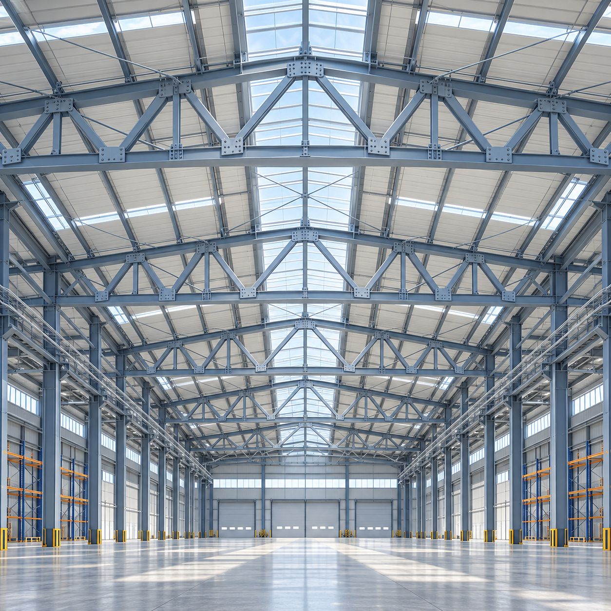
A long-span roof is often judged by one visible result: how much open floor area it creates. For technical evaluators, however, the real question is not simply whether a roof can span 24, 30, or 36 metres without interior columns. It is whether the selected Steel Truss Structure can carry the actual loads, control movement, fit within transport and erection constraints, and remain economical once connections, coatings, maintenance access, and downstream equipment are included.
This distinction matters most in buildings where internal columns interrupt operations rather than merely reduce floor flexibility. Production halls, sports facilities, aircraft shelters, logistics buildings, agricultural facilities, and food-processing plants all depend on clean circulation routes. In these projects, the roof structure becomes part of the operational layout. A poorly selected truss can create excessive deflection, difficult site assembly, congested services, or unnecessary steel tonnage. A well-selected one gives the building a clear and dependable working volume.
Begin with the functional span, not the nominal span
“Clear span” can be misleading if it is taken directly from an architectural grid. The structural span is usually measured between the main supports, but the usable span must account for columns, wall bracing, crane brackets, rail supports, suspended equipment, and service zones near the eaves.
Before comparing truss alternatives, define what must remain unobstructed beneath the roof. A warehouse may only need clear forklift movement. A manufacturing facility may require a continuous overhead conveyor. A processing hall may need hygienic access around machinery, rail systems, chilled rooms, and washdown zones. These conditions influence truss depth, panel layout, support positions, and local reinforcement long before member sizes are calculated.
A practical design brief should identify:
- Required clear width and minimum clear internal height;
- Roof geometry, including slope, parapets, drainage arrangement, and skylight zones;
- Roof-mounted plant, suspended services, solar panels, ceilings, and maintenance loads;
- Crane, monorail, conveyor, or overhead rail loads, including dynamic effects;
- Local wind, snow, seismic, corrosion, and temperature conditions;
- Whether future equipment changes may introduce concentrated loads.
Evaluators should be cautious when a proposal states only a maximum span. A 30-metre truss supporting lightweight roofing in a low-wind area is not comparable to a 30-metre truss carrying snow drift, ductwork, photovoltaic arrays, and moving process loads. The load path, not the span figure alone, determines the appropriate solution.
Choose the truss form around load behaviour and building depth
Steel roof trusses work efficiently because the top and bottom chords carry compression and tension while web members distribute shear through triangulation. Yet not every truss profile performs equally well in every building.
Pratt trusses are often suitable where gravity loading is dominant and economical repetitive web geometry is desired. Their diagonal arrangement can be practical for conventional industrial roofs. Warren trusses, with alternating triangular panels, can offer a clean and balanced appearance and are frequently considered for regular distributed roof loads. Fink trusses are commonly used in pitched-roof applications where panel geometry follows the roof slope. For larger clear spans or significant suspended loads, parallel-chord trusses can provide a level lower chord for services and ceilings, although their depth must be carefully coordinated with clear-height requirements.
The truss depth is one of the earliest decisions with major cost consequences. A shallow truss may preserve headroom but requires heavier chords and can become less efficient under deflection limits. A deeper truss often reduces chord force and material demand, but it can increase building height, cladding area, wind exposure, transport difficulty, and visual bulk. There is no universal ideal ratio. The best depth emerges from structural analysis, roof profile, service coordination, and the cost of the entire envelope—not from a rule copied from another project.
Deflection is often the decision point that steel weight does not reveal
Strength checks establish whether members can resist factored loads without failure. Serviceability checks determine whether the completed roof behaves acceptably in daily use. For long-span roofs, serviceability is frequently the governing issue.
Excessive vertical deflection can cause ponding on low-slope roofs, damage brittle finishes, misalign roof drainage, affect suspended equipment, or create visible sag that worries building owners even when the structure remains safe. Horizontal movement may also affect glazing, cladding interfaces, and bracing connections. When overhead rails or conveyors are attached to the truss system, local and global movement must be assessed together.
Technical reviewers should request deflection criteria explicitly stated in the design basis. They should also ask whether calculations include:
- Dead load, imposed roof load, snow load, wind uplift, and load combinations required by the project code;
- Long-term effects where relevant, including roof-system behaviour and drainage sensitivity;
- Concentrated suspended loads at realistic attachment points rather than idealized uniform loading;
- Dynamic allowances for moving rail, conveyor, hoist, or mechanical equipment loads;
- Compatibility between truss movement and cladding, gutters, ceilings, and service supports.
A proposal with lower steel consumption is not automatically more efficient if it achieves that number by adopting deflection limits that are unsuitable for the roof system or the process below it. The steel frame should support the building’s operational tolerance, not merely pass a minimum strength calculation.
Connection design deserves the same scrutiny as the truss members
In a fabricated truss, connections determine whether calculated forces can be transferred safely and whether the structure can be assembled reliably on site. Chord-to-web nodes, splices, bearing connections, purlin cleats, bracing gussets, and column interfaces all need to be considered as part of one system.
Shop-welded nodes generally offer better dimensional control and reduce high-level site welding. Bolted site splices are often necessary when trusses exceed transport limits or when lifting capacity is restricted. The splice location should be selected around force distribution, erection sequence, and access—not simply at the midpoint because it appears convenient on a drawing.
For evaluators, the key questions are straightforward but important: Are bolts specified by grade and diameter? Are slip-critical or bearing-type connections appropriate for the load condition? Is there enough access for tightening and inspection? Are weld categories, weld sizes, and non-destructive testing requirements defined? Have gusset plates been detailed to avoid water traps and inaccessible coating areas?
Connection congestion is a common warning sign. If too many members meet at a small node, fabrication becomes difficult, weld access is restricted, and geometric deviations become more likely. A slightly more generous panel arrangement can sometimes reduce this risk more effectively than forcing an overly dense theoretical design.
Fabrication tolerances and transport strategy shape the real project outcome
A Steel Truss Structure is not only an engineering model; it is a physical assembly that must be cut, welded, coated, loaded, shipped, lifted, and aligned. Long-span roofs are particularly sensitive to accumulated tolerance. Small errors in camber, splice positioning, chord straightness, or bearing level can become visible once the roof sheets and gutters are installed.
Factory capability should therefore be reviewed alongside calculations. For prefabricated steel buildings, it is useful to confirm the production workflow: material traceability from certified mills, CNC cutting accuracy, qualified welding procedures, dimensional inspection, coating-thickness checks, and packing methods that protect connection surfaces during transport.
Transport often decides whether a full-length truss is realistic. Road width, container dimensions, port handling, local permits, and site access may require the truss to be divided into modules. Modularization should not be treated as an afterthought. It changes splice forces, erection time, crane planning, temporary stability requirements, and the amount of elevated work.
For overseas projects, a manufacturer with export packing experience can add practical value. Clear member marks, coordinated packing lists, bolt segregation, assembly drawings, and 3D erection guides help prevent costly confusion after delivery. This is especially relevant when installation teams are working with a structure fabricated in another country.
Look beyond the roof frame: purlins, bracing, and diaphragm action matter
Main trusses receive most of the attention, but a long-span roof depends on secondary members and stability systems to perform as intended. Purlins transfer roof loads to the trusses; roof bracing collects longitudinal forces; wall bracing transfers them to foundations; cladding and roof sheeting may contribute diaphragm action only when designed and detailed for that purpose.
Secondary steel should be sized for more than vertical gravity load. Wind uplift can govern purlin design in exposed locations, while purlin lap arrangements, sag rods, bridging, and restraint conditions influence their capacity. The roof bracing layout must also respect skylights, smoke vents, ducts, and equipment penetrations. If bracing is left until after mechanical coordination, the apparent clear-span benefit can be undermined by late conflicts.
Column-free does not mean bracing-free. It means the necessary lateral-load system has been placed deliberately at roof, wall, gable, or core locations where it does not interfere with use of the building.
When process loads control the selection
Some facilities cannot be designed as generic sheds. Meat-processing buildings are a good example because the roof structure may support dynamic overhead rail loads while enclosing chilled, frozen, packing, and dispatch zones. In these environments, the frame must follow the process line rather than force the process line around the frame.
For a 3,000 m² facility, column-free process halls in the 24–36 m range may be required alongside floor live loads of 5–25 kN/m² and localized equipment-platform demands. Overhead rails carrying 400 kg or more per rail introduce moving point loads that should be reinforced locally at rail lines, eaves, or designated truss nodes. Spreading these demands across the entire roof through conservative assumptions can add unnecessary tonnage; ignoring their dynamic nature is even more problematic.
In a project such as a Steel Structure Meat Processing Plant, corrosion protection and cleanability are inseparable from structural selection. Hot-dip galvanizing, duplex coating systems, sealed or drainable details, and smooth accessible junctions may be needed where blood, condensate, washdown chemicals, and cold temperatures are present. Steel detailing must be coordinated with insulated food-grade panels, drainage falls, and the hygiene requirements of HACCP-, FDA-, or USDA-oriented operations.
A useful comparison matrix for technical evaluation
Do not evaluate quotations by tonnes alone
Steel consumption is useful as an early benchmark, but it should never be the only measure of value. Two quotations with similar total tonnage may differ substantially in coating scope, connection detailing, testing, secondary steel, design responsibility, documentation, and erection complexity. Conversely, a heavier scheme may be justified when it reduces site welding, improves movement control, accommodates future loads, or performs better in a corrosive environment.
Ask suppliers to provide a scope breakdown rather than a single weight figure. The comparison should distinguish primary trusses, columns, purlins, bracing, connection plates, bolts, protective coating, roof accessories, and design services. Confirm whether foundation reactions are supplied and whether the design includes temporary stability requirements during erection.
For projects sourced internationally, it is also sensible to review quality-control records before shipment. Material certificates, weld inspection records, coating reports, dimensional checks, and third-party inspection arrangements can give the evaluator more confidence than general statements about manufacturing quality. A factory with substantial fabrication capacity can be an advantage, but documented control is what makes that capacity dependable on a specific project.
The final choice: a balanced, buildable roof system
Selecting a long-span truss is an exercise in balancing competing requirements. The lightest frame is not always the most economical. The deepest truss is not always the most efficient. The lowest initial quotation may omit the checks and details that protect performance in service.
A sound selection is one where the structural concept matches the building’s use, the load path is transparent, deflection criteria are appropriate, connections are buildable, coatings suit the environment, and the truss can be transported and erected without improvisation. When those conditions are met, minimal interior columns become more than an architectural ambition. They become a practical, durable asset for the people and processes working beneath the roof.
We are more than happy to serve you here. If you have any question, please feel free to contact us.