
Related Posts
- ▶ Can a Steel Industrial Workshop Be Built Near Residential Areas?
- ▶ Natural or Mechanical Ventilation for Steel Industrial Workshops?
- ▶ Which Insulation Is Best for a Steel Industrial Workshop?
Online Message
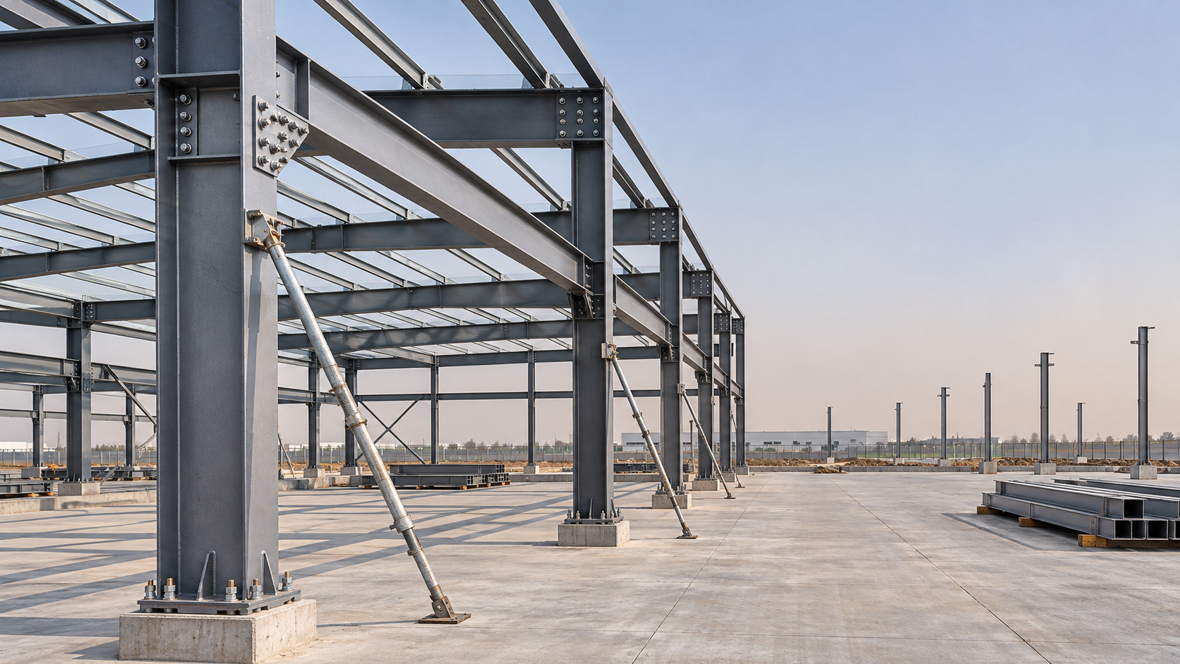
Steel Structure Design and Fabrication connects engineering intent with the reality of construction. A frame that looks straightforward on a design drawing may involve thousands of decisions about connections, tolerances, coatings, transport and lifting. For a project manager, the challenge is not simply to obtain steel components on time; it is to make sure those components arrive with the right documentation and can be erected safely in the planned sequence.
This guide follows that path from design inputs to site assembly. It focuses on the decisions that influence procurement, inspection and construction, particularly when a prefabricated steel building is manufactured in one country and installed in another.
Start with the design basis, not the steel order
Before members are sized or fabrication begins, the project team needs an agreed design basis. This document brings together the assumptions that the structural engineer will use and that the fabricator must understand. Changing them later can affect connection details, material quantities and delivery dates.
Key inputs typically include:
- Building use and geometry: spans, heights, clearances, future expansion and equipment requirements.
- Actions and load combinations: permanent and imposed loads, wind, snow, seismic actions and any crane or machinery loads applicable to the site.
- Site conditions: foundation interfaces, exposure, access restrictions and environmental conditions relevant to corrosion protection.
- Performance requirements: deflection limits, fire resistance, serviceability, durability and intended design life.
- Construction constraints: available lifting equipment, transport limits and the anticipated erection sequence.
These inputs need to reflect the actual project location. A warehouse frame designed for one wind or seismic environment should not be transferred to another without engineering review. Similarly, adding a suspended conveyor or rooftop equipment after the frame is designed can change the load path through members and connections.
Which steel design and fabrication standards apply?
The applicable requirements depend on the jurisdiction, contract and project type. The structural engineer and relevant authorities determine the governing design code; the fabrication and inspection requirements should then be identified in the project specification. Do not assume that a material grade or certificate accepted on a previous job will automatically satisfy a new contract.
Commonly encountered references include the AISC specifications and AWS welding codes in US-based projects, the Eurocodes and EN 1090 framework in European projects, and applicable AS/NZS standards in Australia and New Zealand. ASTM standards may specify steel products, bolts or testing requirements, depending on the selected material and application. The edition, scope and any local amendments matter as much as the standard’s name.
For procurement, ask the engineering team to produce a standards matrix covering structural design, materials, welding, bolting, coatings, tolerances and inspection. Where imported steel or fabricated components are proposed, confirm equivalence and acceptance requirements before purchase. Material test certificates should identify the supplied product and be traceable to the relevant members or production records.
Certification is not a substitute for project-specific checks
A manufacturer may present ISO certification, CE documentation or evidence of compliance with AS/NZS and ASTM requirements. Project managers should verify the exact certificate, applicable standard, scope, issuing body and validity, as relevant to the purchase. These documents do not by themselves establish that every member, weld or coating meets the project specification. The inspection and test plan still needs to define what will be checked and who will accept it.
From structural model to shop drawings
Design drawings communicate the engineer’s intent: member sizes, structural arrangement, connection forces and essential details. Shop drawings turn that intent into fabrication instructions. They identify individual parts, dimensions, bolt holes, welds, assembly marks and surface treatments. Erection drawings explain where the finished assemblies belong and how they relate to the site layout.
The transition between these documents is a common source of delay. A shop drawing may be dimensionally complete but still rely on an unresolved foundation detail, an assumed bolt grade or an opening that clashes with building services. A coordinated model can reveal many conflicts, but it does not replace engineering review or a clear approval process.
Before releasing drawings for fabrication, the project manager should confirm:
- The latest design revisions and connection loads are available to the detailer.
- Connection design responsibility is assigned, including any delegated design and approval requirements.
- Anchor-bolt settings, base plate details and foundation elevations are coordinated.
- Openings, secondary steel, cladding interfaces and equipment supports have been reviewed.
- Drawing status, revision control and the route for technical queries are understood by all parties.
Approval of shop drawings should follow the contract’s defined scope. It does not automatically transfer design responsibility or remove the fabricator’s obligation to check its own work.
Fabrication: where details become physical
Once drawings are released and materials are accepted, fabrication generally moves through cutting, drilling or punching, assembly, welding, dimensional checks and surface treatment. The order varies with the component and production method. Large assemblies may be built in sections to suit the factory, transport route or site lifting capacity.
Traceability matters throughout. Heat numbers and material certificates need to be linked to the relevant production records in the manner required by the specification. If a nonconforming plate or member is found, that link makes it possible to determine what else may be affected rather than holding an entire shipment without direction.
Welding, bolting and tolerances
Weld quality depends on more than appearance. The project may require qualified welding procedures, appropriately qualified personnel, controlled consumables and inspection at defined stages. Depending on the connection, applicable code and inspection plan, examination may include visual inspection and specified nondestructive testing. The extent and acceptance criteria should be agreed in advance rather than negotiated after fabrication.
Bolted connections deserve similar attention. Bolt assemblies must match the specified grade, dimensions and installation requirements. Where slip resistance or pretension is required, the installation method and verification procedure need to be clear to the site team.
Dimensional tolerances are equally important. Hole positions, member length, camber and connection geometry affect whether the frame fits during erection. Tolerances should be read together: a fabricated member can be within its permitted limits while a foundation or adjacent component is also at the edge of its own tolerance. Interface checks reduce the risk of discovering that combination at height.
Coating decisions belong upstream
Paint, galvanizing and other protective systems should be selected for the exposure conditions and required service life, with surface preparation and inspection requirements stated in the specification. Connection surfaces, weld areas and site repairs need particular attention. For example, a coating system may require treatment of areas damaged during transport or field welding before final acceptance.
Fire protection is a separate design consideration. Its need and performance requirements depend on the building, jurisdiction and fire strategy; corrosion protection alone should not be assumed to provide fire resistance.
Plan inspection around decisions, not just documents
An inspection and test plan is most useful when it tells the team when work can proceed and when it must pause. It should identify inspection stages, acceptance criteria, responsible parties, records and any hold or witness points required by the contract.
A practical plan may cover incoming material verification, fit-up before welding, weld examination, dimensional inspection, surface preparation, coating checks and final marking. It should also explain how nonconformities are recorded, assessed, corrected and closed. Repair methods that affect structural work may require engineering approval before they are carried out.
For overseas procurement, agree early on which records will travel with the shipment and which will be reviewed digitally. A typical handover package can include approved drawings, material certificates, inspection reports, coating records, packing lists and a register of open items. Requirements vary, but the principle is constant: the site team should not have to reconstruct the history of a component from scattered emails.
Design the delivery around erection
A container or truck arriving full of steel is not necessarily a useful delivery. If the first columns are buried behind later roof members, the crew may spend valuable crane time sorting material. The erection sequence should therefore inform piece marks, packing groups and dispatch priorities.
Before shipment, review the maximum transport dimensions and weights, lifting points, unloading space, storage conditions and access to the foundations. Protect coated surfaces and keep small items such as bolts and connection plates identifiable. Site teams also need a method for checking delivered pieces against packing lists and reporting damage or shortages promptly.
At the site, verify anchor-bolt positions, foundation levels and bearing surfaces before lifting begins. The erection plan should address crane selection, lifting operations, temporary bracing, stability at each stage, weather limits and safe access. Permanent bracing and connections should be installed as required by the approved sequence; an incomplete frame may not behave like the finished structure shown on the design model.
Field modifications are another control point. Cutting, drilling or welding a member to make it fit can affect its capacity or protective system. Raise the issue through the agreed technical query process and obtain the necessary engineering authorization before changing the steel.
Different structures demand different priorities
A long-span industrial building may put particular emphasis on crane loads, column alignment and roof-member deflection. A multistorey frame may require close coordination of floor levels, stability systems and construction sequencing. Both benefit from early collaboration between the designer, detailer, fabricator and erector, but their critical interfaces are not identical.
Bridge work introduces another set of considerations. Steel Landscape Bridge Systems can span distances in infrastructure, transportation and architectural settings, carrying pedestrians, vehicles or other specified loads. Their strength and adaptability can support varied forms, but the design must address the actual use, fatigue where applicable, bearings, movement, drainage and exposure. The relevant bridge requirements should be established separately from those used for a typical building frame.
What to confirm with a prefabrication partner
For a project manager comparing manufacturers, capacity is useful only when understood alongside the project’s technical and logistical needs. The manufacturer described for this service operates a 120,000 m² plant with a stated output of 100,000 tonnes per year and supplies factory-direct steel structures to more than 20 countries. Those figures help establish the scale of the operation; they do not replace a review of current production availability, project scope or delivery constraints.
Ask prospective suppliers to explain how they manage drawing revisions, material sourcing, traceability, subcontracted processes and inspection access. Review their stated ISO, CE, AS/NZS and ASTM credentials against the actual documentation and project requirements. It is also worth asking who resolves technical queries, how components are packed by erection sequence and what records are provided at handover.
Good steel structure design and fabrication is a continuous chain of coordinated decisions. When the design basis, shop details, inspection plan and erection sequence are aligned early, the project team has a clearer route from drawings to a stable, completed frame—and fewer surprises waiting at the jobsite.
We are more than happy to serve you here. If you have any question, please feel free to contact us.