
Related Posts
- ▶ Can a Steel Industrial Workshop Be Built Near Residential Areas?
- ▶ Natural or Mechanical Ventilation for Steel Industrial Workshops?
- ▶ Which Insulation Is Best for a Steel Industrial Workshop?
Online Message
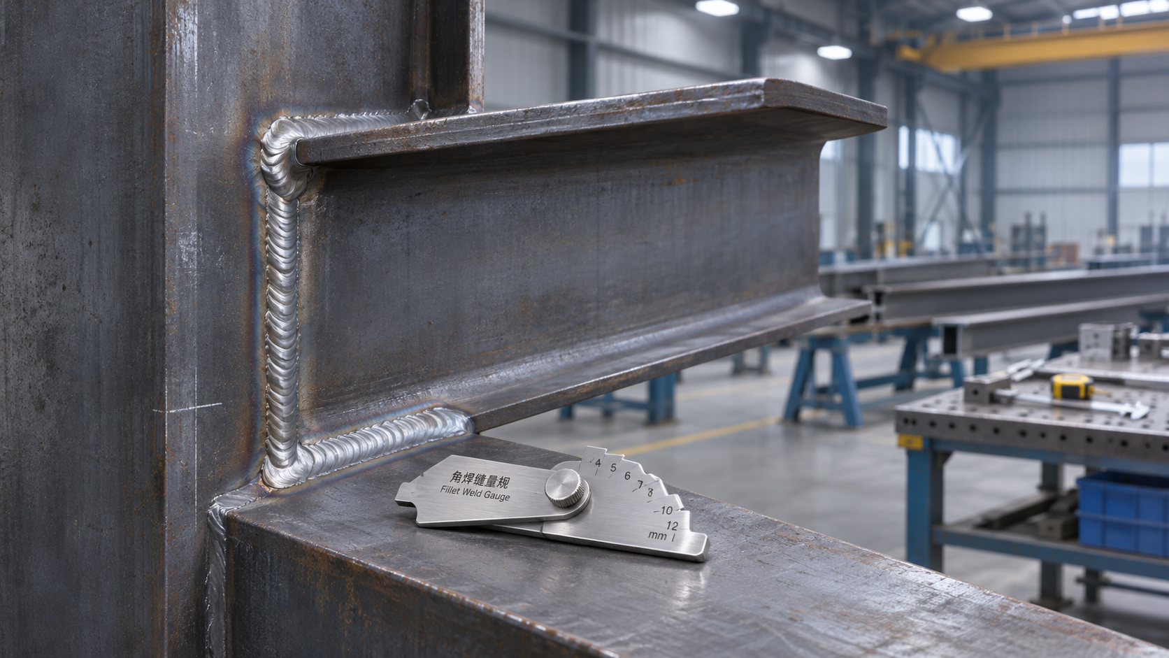
A weld can look smooth and still contain a flaw that affects the performance of a steel connection. Acceptance therefore depends on more than appearance: the weld must meet the requirements specified for its joint, be inspected at the required stages, and have a traceable record of the results. In Steel Structure Design and Fabrication, those requirements should be settled before production starts, when there is still time to address access, testing, and repair constraints.
A practical inspection program follows the weld from preparation through final release. It also distinguishes between an indication found during testing and a defect that exceeds the applicable acceptance criteria. That distinction prevents both unsuitable welds from being shipped and unnecessary repairs that can introduce new problems.
Start with the acceptance basis, not the appearance of the weld
Before inspecting a fabrication, establish which code, edition, drawings, specifications, and approved inspection and test plan apply. Structural welding requirements vary by jurisdiction and project. A project may use AWS D1.1, EN 1090 with related European welding standards, or an Australian and New Zealand structural steel welding standard, depending on its contractual and regulatory framework. These systems are not interchangeable sets of limits that can be mixed to obtain a preferred result.
The governing documents should identify the welds, their required sizes and joint details, the inspection methods, the extent of testing, and the acceptance criteria. They should also establish who can approve departures, repairs, and final release. Where drawings and specifications conflict, resolve the discrepancy through the project’s documented technical process before the affected work proceeds.
Pay particular attention to joints with demanding load paths, cyclic loading, restricted access, or consequences of failure that justify additional scrutiny. A splice in a heavily loaded member may need a different inspection approach from a small attachment weld. The design documents and project requirements determine that approach; the inspector should not infer it solely from the weld’s visual appearance.
What to inspect before welding starts
Many weld problems begin before the arc is struck. Confirming the following conditions at fit-up can prevent defects that are difficult to correct once a joint is closed:
- Material identification: Check that the steel and welding consumables match the approved documents and remain traceable through fabrication. Material mix-ups can affect the suitability of the welding procedure and the performance of the connection.
- Joint preparation: Check the joint type, bevel, root opening, alignment, and backing where applicable against the approved detail and welding procedure. Poor fit-up can lead to incomplete fusion, excessive distortion, or an incorrect finished weld size.
- Surface condition: Remove contaminants from the welding area as required by the procedure. Oil, moisture, heavy rust, and unsuitable coatings can interfere with welding or inspection.
- Procedure and personnel: Verify that the applicable welding procedure is available and that welders or welding operators hold the qualifications required for the work. Confirm that consumable control, preheat, and other specified conditions can be maintained.
- Inspection access: Consider whether the completed joint can be visually examined and whether the specified nondestructive testing equipment can reach the required areas. Access problems discovered after assembly may require additional work or an approved change.
Fit-up checks are especially useful on repetitive shop work. An incorrect detail repeated across a batch of beams or columns can produce many nonconforming welds before final inspection reveals the underlying cause. A documented check on the initial assembly and appropriate checks during production help control that risk.
Inspection during welding and after completion
During fabrication, inspection focuses on whether the work continues to follow the approved procedure. Depending on the joint and inspection plan, this may include checking preheat and interpass temperature, consumable condition, cleaning between passes, and removal of temporary welds or defects before subsequent passes cover them.
Monitoring matters because some conditions cannot be judged reliably from the finished surface. For example, a final bead may conceal inadequate cleaning between passes. Similarly, a joint that was assembled outside the permitted fit-up range may have been welded using a procedure that no longer suits the actual conditions.
After welding, visual inspection should cover the accessible weld surface and adjacent base metal. The inspector checks location, continuity, profile, apparent size, and visible discontinuities against the drawing and applicable acceptance criteria. A fillet weld gauge can help assess size and profile, but the reading still needs to be interpreted against the specified weld and the relevant rules for measurement.
Inspection timing matters. The inspection plan should state when final examinations are to be performed, including any waiting period required for the material, joint, or governing code. Coatings can conceal surface conditions and interfere with some tests, so the sequence for inspection, repair, and surface preparation should be agreed before painting or galvanizing.
Common weld discontinuities and what they mean for acceptance
A discontinuity is an interruption in the normal structure or shape of a weld. It becomes a rejectable defect when it fails the applicable acceptance criteria. The same type of indication may be treated differently depending on its size, location, weld type, loading condition, and governing standard.
Do not assume that grinding a visible imperfection makes the weld acceptable. The remaining weld must still meet the required dimensions, and grinding must not damage the base metal or leave an unacceptable transition. If an indication extends below the surface, its full extent needs to be addressed through the approved repair process.
Choosing weld inspection and testing methods
Visual testing is the foundation of weld inspection because it can identify fit-up problems, missing welds, incorrect profiles, and accessible surface discontinuities throughout fabrication. It cannot reliably reveal flaws buried inside the weld. Additional nondestructive testing, often abbreviated to NDT, is selected according to the joint, material, access, and project requirements.
Magnetic particle testing is used on suitable ferromagnetic materials to find surface and near-surface indications. Liquid penetrant testing can reveal discontinuities open to the surface on suitable nonporous materials. Both depend on appropriate surface preparation and access. Neither is a general substitute for a method intended to examine the weld volume.
Ultrasonic testing uses sound waves to examine material below the surface and can be useful for internal discontinuities. Its effectiveness depends on factors such as joint geometry, material thickness, surface condition, access, and the technique used. An indication on an ultrasonic report must be assessed under the specified procedure and acceptance criteria; it is not automatically a rejectable defect.
Radiographic testing produces an image that can reveal certain internal discontinuities. It has different access, safety, and interpretation requirements from ultrasonic testing, and sensitivity varies with the type and orientation of a discontinuity. Selecting one method solely because it is perceived as more advanced can leave the wrong area or flaw type inadequately examined.
The inspection plan should specify the method, extent and locations of testing, applicable procedure, personnel qualifications, and reporting requirements. Where sampling is permitted, it should also state how locations are selected and what happens if a tested weld fails. A percentage alone is not a complete sampling plan: the project needs a defined response to a failed sample, including any expanded inspection.
How to handle a failed inspection
When a weld does not meet the specified criteria, identify the affected component and location, record the finding, and prevent the item from being released while the nonconformance remains open. The disposition may involve an approved repair, removal and replacement, or a formal engineering assessment where the project permits one. An inspector should not independently accept a departure that requires design authority approval.
A repair plan should address how the unacceptable material will be removed, how the excavation will be checked, which welding procedure will be used, and which examinations will be repeated. Repairs can introduce heat, distortion, or new discontinuities, so they should be controlled rather than treated as routine cosmetic work. Reinspection must cover the repaired area and any additional area required by the governing documents.
Repeated failures also call for a process review. If similar lack-of-fusion indications appear in several joints, for example, repairing each weld without examining fit-up, technique, and procedure compliance may allow the same problem to continue through the production run.
Keep the release record connected to the component
A useful inspection record allows someone receiving the steelwork to connect a physical member and weld to the applicable drawing, inspection result, and any repair. The level of detail depends on the project, but a release package commonly brings together material traceability, welding procedure and qualification records, inspection reports, NDT reports, nonconformance dispositions, and final acceptance records.
Check that reports identify the tested locations and the acceptance criteria used. A report stating only that ultrasonic testing was “satisfactory” is less useful if it does not show which welds were examined, what procedure applied, or how the results relate to the member marks. Third-party inspection can provide an additional witness or review point when specified, but it does not replace the fabricator’s own production controls.
Coordination with the building envelope also belongs in the release sequence. Roof and wall attachments, openings, and support details should be resolved against the frame drawings before fabrication closes off access or coatings are applied. A coordinated Steel Building Envelope System can help define those interfaces; structural weld acceptance still rests on the specified joint requirements and inspection records.
Before shipment, reconcile open inspection items with the component list. A member is ready for release when the required examinations are complete, any nonconformances are closed through the proper authority, and the records demonstrate acceptance against the project’s specified criteria.
We are more than happy to serve you here. If you have any question, please feel free to contact us.