
Related Posts
Online Message
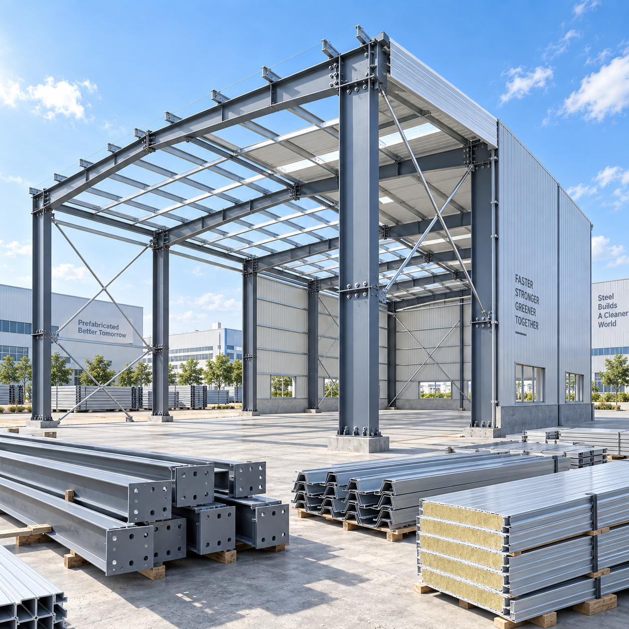
Pre Engineered Steel Buildings Explained: Components, Benefits, and Typical Uses
Pre Engineered Steel Buildings are changing the practical side of construction for warehouses, factories, workshops, logistics facilities, and straightforward commercial spaces. The idea is not simply “build with steel.” It is to resolve much of the structural design, detailing, fabrication, marking, and connection work before materials arrive at the project site. The site team then assembles a coordinated package rather than cutting, drilling, and adapting major members in the field.
That distinction matters. A conventional steel project can also use fabricated members, but a properly pre-engineered system is designed as an integrated building: primary frame, secondary steel, roof and wall enclosure, bracing, openings, drainage, and connection details need to work together. When the package is well coordinated, erection becomes largely a bolting operation. When it is not, the apparent speed advantage can disappear into site modifications, missing interfaces, or foundation misalignment.
For researchers comparing construction options, the useful question is not whether a steel building is “better” in every situation. It is whether the building has a repetitive, clear-span, schedule-sensitive, or labor-constrained profile that makes factory-led engineering worthwhile.
What Makes a Building “Pre-Engineered”?
A pre-engineered building, often called a PEB or PEMB, is a steel structure whose main elements are designed and fabricated to suit a defined project before shipment. The building is not necessarily a standard off-the-shelf kit. In fact, the better systems are usually tailored to the site’s span, height, wind and snow exposure, seismic requirements, internal equipment loads, cladding choice, and local code basis.
The term “pre-engineered” can be slightly misleading because engineering still has to be done. It means the engineering is completed upstream, with drawings and fabrication controlled in a factory environment rather than being improvised during erection. Steel members are cut, welded, drilled, inspected, labeled, and packed against approved shop drawings. Complex connections may be trial-fitted before dispatch. This gives the installation crew a much clearer sequence and reduces the need for field fabrication.
A typical Pre-Engineered Metal Building (PEMB) System is therefore best understood as a coordinated delivery method, not just a category of steel frame. It can include structural design, 3D detailing, manufacturing, export packing, erection drawings, and, where needed, localized installation guidance or site supervision.
The Parts That Actually Carry and Enclose the Building
Most pre-engineered steel buildings look simple after completion: columns, roof, wall panels, doors. Underneath that simplicity is a hierarchy of components. Knowing what each one does makes it easier to compare quotations and spot scope gaps early.
Primary framing: columns and rafters
The primary frame is the main load-carrying skeleton. It commonly consists of rigid frames made from columns and rafters, often using welded H-shaped or tapered members. Tapered sections put more steel where bending forces are highest and less where it is not structurally necessary. This is one reason a well-designed pre-engineered frame can be materially efficient without being under-designed.
Rigid frames are especially effective for open interiors. In ordinary manufacturing or storage buildings, spans in the range of 15–40 m are common within a PEMB system, while eave heights may fall around 6–12 m. These figures are not universal design limits; crane loads, local climate loads, mezzanines, fire requirements, and building use can alter the appropriate layout significantly.
Secondary steel: purlins, girts, and eave members
Secondary framing supports the roof and wall cladding and transfers those loads back to the main frame. Roof purlins run along the roof slope, while wall girts run horizontally across the walls. Eave struts connect the roof and wall zones. These members are often cold-formed Z or C sections, selected according to spacing, cladding load, wind pressure, and continuity requirements.
This is a part of the building that is easy to underestimate. A quote that lists “steel frame” but is vague about purlin thickness, galvanizing, bridging, or connection hardware is not yet a full building comparison. Secondary steel affects cladding support, diaphragm behavior, and the ease of installing insulation, skylights, and service penetrations.
Bracing and connection systems
Wind and seismic forces need a route to the foundations. Rod bracing, angle bracing, portal bracing, flange braces, and diaphragm action from roof and wall systems all contribute depending on the design. The exact arrangement should be coordinated with doors, windows, conveyor openings, and internal circulation. A large loading door placed where cross-bracing was expected is a familiar source of late-stage redesign.
Connections are equally important. In export-oriented fabrication, bolt holes are generally drilled in the factory rather than punched or created on site. Components should be marked by grid location and erection sequence, with bolts and drawings matched to the packing list. That may sound procedural, but it is what allows a small site crew to work efficiently instead of spending days identifying similar-looking members.
Roofing, wall cladding, insulation, and accessories
The enclosure system protects the frame and determines much of the building’s day-to-day performance. Options may include single-skin metal sheets, insulated sandwich panels, built-up insulated roof systems, translucent panels, louvers, ridge ventilators, gutters, downpipes, personnel doors, roller shutters, and windows. The right selection depends less on appearance than on condensation risk, indoor temperature requirements, fire strategy, acoustic needs, and expected maintenance.
In humid or coastal environments, coating selection deserves early attention. Hot-dip galvanizing, a blast-cleaned Sa2.5 surface with epoxy zinc-rich primer, duplex protection combining galvanizing and a paint topcoat, or a marine-grade coating may be considered according to corrosion exposure. There is no single “best” finish. The steel environment, expected service life, access for maintenance, and compatibility of fasteners and cladding should be reviewed together.
Why These Systems Often Save Time—And Where They Do Not
The strongest advantage of Pre Engineered Steel Buildings is predictability. Because the frame is modeled and detailed before production, fabrication can proceed while the foundation work is being prepared. Once the anchors are set correctly and materials arrive, the building can move from frame erection to enclosure without the same volume of field cutting and welding associated with less coordinated construction.
This is particularly valuable on overseas projects where experienced steel labor is limited, costly, or difficult to mobilize. It also suits repeat facilities across several sites, where the owner wants a consistent structural concept but may need local adjustments for climate, ground conditions, or regulations. A China-based manufacturer with a large fabrication plant, traceable mill materials, and export documentation capability can help centralize this upstream work—provided the engineering basis is aligned with the destination project.
Speed should not be confused with immunity from planning mistakes. A PEMB package cannot correct poorly surveyed foundations, uncertain soil conditions, late decisions on crane capacity, or uncoordinated mechanical openings. In practical terms, the system rewards early decisions. The more core information is locked before shop detailing begins, the more reliable the schedule becomes.
Typical Uses and the Limits of the “Standard Building” Idea
Warehouses and distribution buildings are obvious applications because they often need open floor area, regular loading access, and a roof that can cover a large footprint efficiently. Manufacturing plants are another common fit, especially where the production layout benefits from clear spans or where overhead crane provisions can be designed into the frame from the outset.
Workshops, agricultural storage, vehicle maintenance facilities, hangar-like shelters, retail depots, and simple commercial buildings can also be suitable. The system is particularly practical for fixed-programme projects and repeat builds. An owner constructing several standard storage facilities does not need to reinvent every structural detail, though each location still requires site-specific loading and foundation review.
The approach becomes less straightforward when a building has highly irregular geometry, heavy point loads at many changing locations, unusually strict architectural demands, complex multi-storey circulation, or extensive field changes expected during construction. Steel can still be the right material in those cases, but a conventional bespoke structural approach may offer more flexibility. A pre-engineered solution is most effective when its discipline matches the project, not when it is forced onto every brief.
Questions Worth Asking Before Comparing Suppliers
Price per tonne is a weak starting point for comparing building systems. It does not tell you whether the same design loads, steel grade, coating life, connection scope, cladding specification, accessories, or documentation are included. It can even reward an incomplete scope that shifts cost and risk to the site contractor later.
A more useful review asks what design standard governs the structure and whether it suits local approval requirements. Steel may be specified as Q355B or Q235B under GB standards, S355JR or S275JR under EN standards, or ASTM A572 Grade 50 in an ASTM/AISC-oriented project. These are not interchangeable labels to be selected casually. The engineering team needs to confirm the grade, material certificates, and applicable structural design code, such as GB 50017, EN 1993, or an AISC-based design route.
It is also worth asking how the structure is modeled, detailed, checked, and documented. Engineering software such as PKPM, 3D3S, Midas, or SAP2000 may be used for analysis, while Tekla-based detailing and BIM models can improve the connection and fabrication workflow. The software name alone is not proof of a sound design; the important point is whether drawings, calculations, fabrication, and site assembly are properly connected.
For international shipments, inspectability matters. Reputable factory processes commonly include certified-mill traceability, weld checks such as ultrasonic testing where specified, regular welding audits, documented quality control, and the option for third-party inspection before shipment. A manufacturer operating under ISO 9001 controls and familiar with CE, AS-NZS, ASTM, or other project requirements may be better prepared for cross-border documentation, but the final compliance package must always be checked against the actual destination and contract scope.
A Sensible Way to Evaluate Fit
Start with the building function, not a frame drawing. Define the required span, eave height, bay spacing, loading doors, internal process equipment, future expansion, roof-mounted services, and any crane requirements. Then establish the site conditions: wind, snow, seismic category, corrosion environment, ground information, and local approval pathway. Only after those inputs are reasonably stable should the building be optimized for fabrication and shipment.
For a routine industrial building, a 6–9 m bay spacing may be an efficient starting point, but it should not be treated as a rule. Door positions, racking lines, fire separation, façade rhythm, and equipment clearances can justify a different grid. Small changes on a plan can have a large effect on bracing and member design, so it is better to settle operational requirements before the supplier begins detailed shop drawings.
Pre Engineered Steel Buildings work best when they are treated as a coordinated building package rather than a pile of steel to be adapted later. For a warehouse, factory, workshop, or repeat-site facility with a clear brief, that coordination can reduce site uncertainty and make the programme easier to manage. The real value is not merely that components arrive prefabricated; it is that the difficult decisions have been made, checked, and communicated before the erection crew is standing on site waiting for answers.
We are more than happy to serve you here. If you have any question, please feel free to contact us.