
Related Posts
Online Message
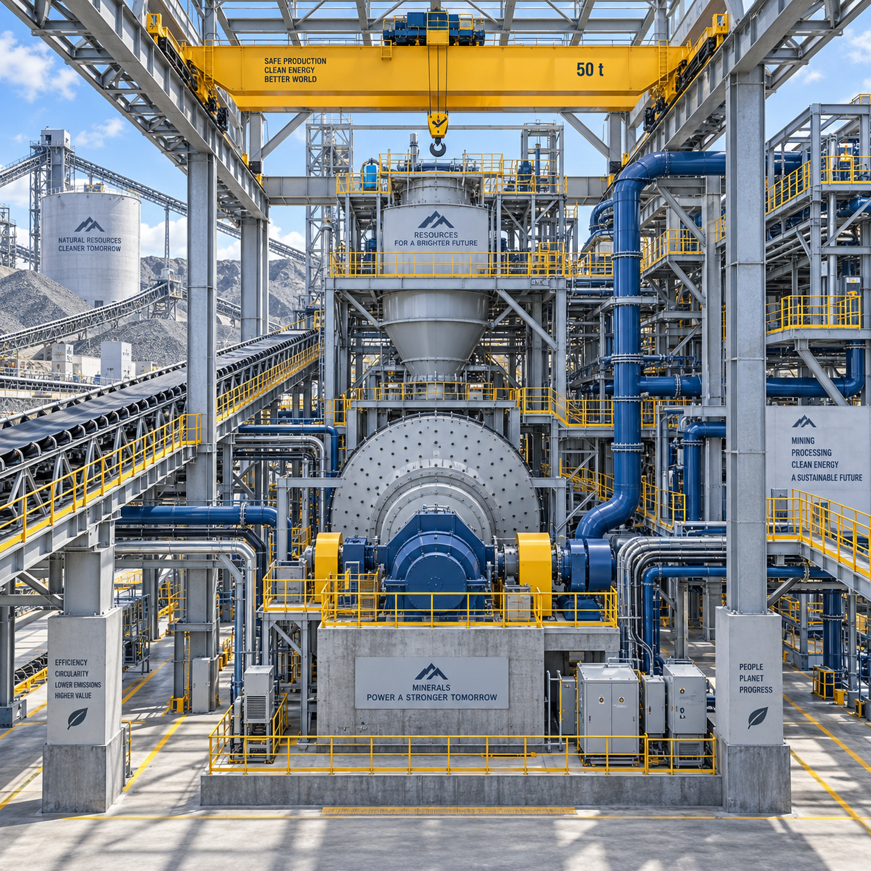
Industrial facilities rarely fail because a steel frame was too simple. Problems usually begin when the structure is treated as a separate package from the process it must support. In mining, energy, and process plant work, the building frame has to accommodate equipment loads, maintenance access, corrosive exposure, pipe routes, lifting operations, and a construction sequence that may be constrained by remote logistics or a live operating site.
Industrial Steel Structures are most effective when they are designed around those operating conditions from the start. A prefabricated steel system can shorten field erection and improve fabrication control, but it does not remove the need for early coordination. The right solution is not simply the lightest frame or the lowest quoted steel tonnage. It is the frame that can be fabricated accurately, erected safely, and maintained without forcing costly changes after equipment arrives.
Start with the process, not the building outline
The first practical question is not “How large is the building?” It is “What must the structure carry, contain, and allow people to do?” A mineral handling station, power-generation auxiliary building, pump house, compressor enclosure, and chemical process unit may all use structural steel, yet their governing requirements are very different.
For example, a conveyor gallery needs support locations that match conveyor drives, transfer towers, walkways, and belt maintenance zones. A process building may need multiple openings for ductwork, pipe racks, vessels, and cable trays. An energy facility may have equipment that creates concentrated reactions, vibration, or thermal movement. If these inputs arrive after the steel shop drawings are released, the correction is rarely minor. Beams may need reinforcement, bracing may block a route, or field crews may be asked to cut new openings into completed work.
Before structural design is fixed, assemble a coordinated load and interface schedule covering:
- Major equipment weights, support footprints, anchor bolt locations, and maintenance removal paths.
- Crane loads, runway beam requirements, hook approach, and lifting clearances.
- Platform, grating, stair, handrail, and access requirements for operations and inspection.
- Pipe rack elevations, cable tray zones, ventilation ducts, and fire protection routing.
- Environmental exposure, including moisture, dust, chemicals, salt air, and temperature variation.
- Foundation interfaces, erection access, transport limits, and site lifting capacity.
This schedule does not need to contain every final detail before procurement. It does need to identify the loads and openings that can change the primary frame. Steel is adaptable, but adaptation is least expensive in the model and most expensive after members are delivered to site.
Different industrial zones need different structural responses
One facility can contain several structural environments. Treating all areas with the same framing arrangement and coating specification can create either unnecessary cost or a weak point in the plant.
Mining applications often demand robust access steel as much as primary framing. Operators need safe routes to inspect drives, clean spillage points, replace rollers, and service instruments. Those routes affect column positions, bracing locations, and platform support reactions. Designing access only after the main structure is complete tends to produce congested platforms and awkward stair layouts.
In process plants, penetrations deserve particular attention. Pipes, ducts, cable trays, vertical risers, and maintenance hatches should be identified in the fabrication model wherever possible. A planned framed opening preserves member capacity and provides a clean interface. A field-cut opening may require engineering review, reinforcement, recoating, and work at height.
Prefabrication helps only when the package is complete enough
Factory fabrication provides real advantages for industrial projects: controlled cutting and welding, repeatable hole locations, better traceability of main members, and less hot work in difficult site conditions. These benefits are especially useful where local weather, limited skilled labor, or remote-site logistics make field fabrication unreliable.
However, prefabrication is not the same as shipping steel early. Releasing fabrication before equipment, civil, mechanical, and electrical interfaces are sufficiently coordinated transfers uncertainty into the field. The result can be a fast delivery of components that do not fit the final process layout.
A workable approach is to divide the steel package by design maturity. Primary frames, standard bracing, and repetitive platform modules may be released once their interfaces are stable. Areas around major equipment, unusual penetrations, expansion joints, or proprietary skids should remain under controlled review until the relevant information is confirmed. This is often more effective than delaying the entire package or issuing all drawings at once.
For overseas supply, the documentation package matters as much as the member list. Erection drawings, assembly marks, bolt schedules, packing lists, connection details, and clear loading plans reduce ambiguity during unloading and installation. Three-dimensional assembly guides can be particularly useful for complex frames with multiple elevations, repeated access platforms, or connections that are difficult to identify from two-dimensional drawings alone.
Corrosion protection must follow the exposure zone
Steel durability is not determined by coating thickness alone. Surface preparation, drainage, connection geometry, damage during transport, and access for later inspection all affect service life. A coating system should therefore be selected for the actual atmosphere and operating exposure, rather than applied uniformly across an entire plant.
Indoor dry areas may need a different treatment from outdoor pipe racks, wash-down zones, coastal utility sites, or areas exposed to chemical vapors. Hot-dip galvanizing can be suitable for many external components and smaller access assemblies. Blast cleaning followed by an epoxy zinc-rich primer and compatible topcoat may be selected where a paint system is appropriate. In highly demanding environments, a duplex approach combining galvanizing and paint can provide an additional protective layer. The selection still has to account for member size, connection design, field repairs, and the expected inspection approach.
Details can undermine a good coating specification. Horizontal ledges that retain water, sealed cavities that trap moisture, inaccessible contact faces, and poorly planned dissimilar-metal interfaces are recurring sources of deterioration. Where wash-down, salt air, or process leakage is possible, build drainage and inspection access into the steel detail instead of relying on maintenance to compensate for a poor geometry.
Do not confuse equipment loads with building loads
Industrial structures are commonly asked to support loads that are intermittent, moving, concentrated, or difficult to describe in a conventional building brief. A large vessel may impose a static reaction, while a crusher, compressor, or pump can introduce vibration and operational movement. An overhead crane creates vertical wheel loads, horizontal surge, and fatigue considerations. Pipe racks may gain weight over time as new lines, insulation, valves, and temporary construction loads are added.
Each condition should be assigned to the correct support system. Some equipment belongs on a dedicated reinforced concrete foundation that is isolated from the building frame. Some equipment can be supported by structural steel if the reactions, stiffness needs, and vibration behavior are understood. Some process units need a hybrid arrangement, with steel support above a civil base. Treating all heavy equipment as “floor load” is too vague to support a reliable design decision.
The same principle applies to future capacity. Leaving spare space on a rack or mezzanine does not automatically mean the structure can support additional equipment. Future loads should be identified as a design allowance, with the affected columns, beams, foundations, and connections checked as a system. A connection may govern before a visible beam appears heavily loaded.
Where multi-level steel framing is useful, and where it is not
Not every industrial process should be spread vertically. A single-level layout is usually easier for heavy equipment replacement, large vehicle movements, and very tall process items. Vertical construction becomes more attractive when land is constrained, the process has a natural upward or downward flow, or lighter production and utility functions need to sit close together without expanding the site footprint.
For lighter manufacturing, assembly, control-room support areas, precision production, or phased capacity growth, a Multi-Storey Industrial Workshop can be a relevant reference point. Its structural logic is different from a commercial multi-storey building: production floors require defined live loads, machinery zones may need local strengthening, and goods movement must be planned through lifts, ramps, or hoist shafts. Composite deck and concrete slab systems can keep floor depth efficient, while framed openings for risers and vertical transport should be coordinated before fabrication.
This arrangement is less suitable when frequent removal of large equipment dominates operations, when extreme point loads are distributed throughout every level, or when vertical material handling would interrupt the process. The decision should follow material flow and maintenance strategy, not simply land cost.
Use capability evidence that matches the package
Supplier selection should go beyond a general statement that a fabricator can produce steel buildings. Ask how the supplier controls the parts that matter for your project: material traceability, welding procedures, dimensional checks, non-destructive examination where specified, coating inspection, packing, and export documentation.
For large or schedule-sensitive packages, manufacturing capacity also affects risk. A fabrication operation with multiple steel production lines, a 120,000 m² manufacturing park, and annual output capacity of 100,000 tonnes may be better positioned to sequence substantial orders than a workshop that relies on intermittent subcontracting. Capacity alone is not a guarantee of delivery, but it makes a meaningful difference when paired with a realistic production schedule, approved drawings, and clear inspection hold points.
Certification should be assessed in the context of the project’s contractual and jurisdictional requirements. ISO 9001 quality management, along with familiarity with CE, AS-NZS, ASTM, or other specified frameworks, can support a controlled supply process. It does not replace project-specific engineering review, approved connection details, or the requirements of the authority governing the site.
A practical release sequence for the steel package
Schedule certainty improves when key decisions are made in the right order. The following sequence keeps the structural package connected to the construction and operating plan:
- Freeze the process layout, major equipment reactions, maintenance routes, and crane concept before finalizing the primary frame.
- Coordinate foundations, anchor bolts, underground services, and base plate levels before fabrication drawings are approved.
- Model major penetrations, pipe rack interfaces, platforms, vertical transport, and equipment-removal openings with the steel frame.
- Define corrosion zones and the associated surface preparation, coating, repair, and inspection requirements.
- Agree on document approvals, inspection points, shipment lots, container loading priorities, and site erection sequence.
- Keep a controlled process for changes after release, including responsibility for design review and the effect on delivery dates.
The most useful early deliverable is often not a steel weight estimate. It is an interface register showing what information controls each frame zone and when that information must be released. This gives the construction team a visible way to distinguish a genuine design dependency from a preference that can be resolved later.
Questions that expose avoidable risk
Can field modifications be assumed?
No. Minor adjustments may be manageable, but drilling, cutting, welding, or relocating bracing can affect strength, fatigue behavior, fire protection, corrosion protection, and approved drawings. Treat any alteration to primary members or engineered connections as a controlled engineering issue.
Is heavier steel automatically safer for industrial use?
No. Excess steel may increase cost, foundation demand, transport weight, and erection difficulty without resolving the real problem. Correct load paths, connection design, stability, access, durability, and equipment interfaces matter more than simply increasing member sizes.
When should a steel package be released for fabrication?
Release when the primary geometry, design loads, foundation interfaces, major openings, and governing process connections are stable. If a zone still depends on unresolved equipment data, isolate it from the early-release package where possible rather than guessing.
A durable industrial facility is built through disciplined coordination: process data defines the structural problem, the fabrication model resolves interfaces, and the site sequence protects the intended quality. When those three elements remain connected, steel framing becomes a practical tool for faster construction and dependable plant operation rather than another source of late-stage change.
We are more than happy to serve you here. If you have any question, please feel free to contact us.