
News center
Related Posts
Online Message
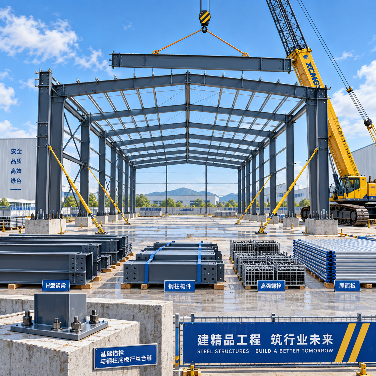
Erection delays in a portal frame steel building usually begin before the first column is lifted. A steel package can arrive on the planned date and still sit idle because anchor bolts do not match the base plates, the crane cannot reach the unloading zone, a missing splice detail stops a frame line, or roof sheets arrive before the secondary steel is stable. The fastest recovery is rarely faster lifting. It is removing the constraint that prevents the next safe, complete sequence of work.
A workable programme should therefore be built around release conditions, not broad milestones such as “steel delivered” or “frame erected.” A portal frame bay is ready to progress only when foundations, components, access, lifting equipment, temporary bracing, connection information, and inspection hold points are all aligned. Treating these as separate workstreams often creates short, repeated stoppages that consume more time than one visible delay.
Freeze the interfaces that control fit-up
Portal frames tolerate little ambiguity at their primary interfaces. Column bases, rafter splices, knee connections, bracing points, crane brackets, wall rails, purlins, gutters, doors, and service penetrations all influence the erection sequence. Fabrication should not proceed on the assumption that a later drawing revision will be easy to absorb. A small change in roof slope, eave height, cladding build-up, or opening position can alter member lengths, connection geometry, bolt access, and drainage details at once.
The foundation survey is a frequent source of avoidable disruption. Before steel leaves the workshop, compare the as-built grid, elevation, bolt projection, bolt spacing, diagonal dimensions, and pedestal dimensions against the approved steel drawings. Checking only the center-to-center spacing of anchor bolts is insufficient. A bolt group may have the correct nominal spacing but be rotated, offset from the gridline, or set at an elevation that leaves no adjustment range beneath the base plate.
Resolve discrepancies with a measured record rather than verbal site reports. The decision may involve local concrete repair, an engineered base-plate modification, a designed shim arrangement, or replacement anchors. Each option affects erection timing differently. Field cutting holes without design approval can reduce edge distance, compromise bearing, and transfer a simple alignment issue into a connection redesign.
Rafter splices deserve the same discipline. Verify the member marks, splice plate orientation, bolt grade, bolt length, washer arrangement, and access for tightening before the lift. A rafter can be physically connected yet still be impossible to tension correctly once it is close to an adjacent member or temporary support. When a site joint has a designated slip-critical or preloaded bolt requirement, the sequence for snug tightening, final tightening, and inspection must be clear before work begins.
Plan the erection sequence around structural stability
A portal frame does not become stable merely because columns and rafters are standing. During erection, the partially completed structure behaves differently from the finished building. Permanent roof bracing, wall bracing, purlins, eave struts, and cladding diaphragms may not yet be in place. Wind, unsymmetrical loading, crane movement, and released rigging can impose forces that the temporary condition was never intended to resist.
The usual productive sequence is to erect and align an initial braced bay, install the required temporary and permanent stability elements, and then extend the frame in controlled increments. The exact bay count depends on the engineer's erection method, frame spacing, member weight, wind exposure, and availability of permanent bracing. Starting multiple disconnected frame lines may appear to increase activity, but it can leave several incomplete areas competing for the same crane, access route, and erection crew while none is ready for secondary steel.
Temporary bracing needs a designed location and release point. It should not be treated as an improvised remedy after a frame begins to drift. Record which braces remain in place, who authorizes removal, and what permanent elements must be complete first. This is especially important where roof bracing is interrupted by skylights, smoke vents, solar support zones, large services, or future expansion joints.
Alignment must be checked before the frame is restrained by purlins and cladding. Correcting a column that is out of plumb after secondary members are installed introduces additional dismantling work and risks damaging coated surfaces. Establish survey hold points after the first frame, after the stabilizing bay, and at sensible intervals along a long building. Confirm grid position, column plumb, eave elevation, ridge line, bay spacing, and roof-plane geometry while adjustments remain straightforward.
Separate delivery completion from erection readiness
A complete shipping list does not guarantee an erectable package. Site teams need loads arranged according to the lift sequence, not only according to workshop convenience or trailer capacity. Columns required for the first frame, rafters for the same bay, splice materials, bracing, bolts, purlins, and temporary works should be locatable without unloading unrelated bundles first.
Each piece should carry a durable mark that agrees with erection drawings, packing lists, and bolt schedules. The critical test is practical: can a crew identify a member from ground level, confirm its orientation, and move it to the pick area without opening multiple bundles? Lost time often comes from a small missing item hidden inside a mixed delivery, particularly a set of flange plates, a bracing cleat, or a connection bolt package.
Transport restrictions can change the preferred fabrication and site assembly plan. Long rafters or trusses may require designed splice points because of route limits, turning radii, permits, or trailer length. Those splices need protected, level assembly space and a known lifting method. A member split for transport is not automatically easier to erect: additional site joints increase bolt handling, inspection work, and the number of components that must arrive together.
Unloading space also needs to protect the steel from distortion and contamination. Store columns and rafters on level dunnage at support points that avoid permanent bending. Keep connection faces out of standing water and prevent bundles from being stacked where a forklift will bend thin wall rails or purlins. Separate roof sheets, insulation, flashings, and fasteners from the primary frame area so cladding materials do not block crane paths or access to base connections.
Make site readiness specific enough to act on
“Site ready” should describe conditions that allow safe, uninterrupted lifting. The crane standing area must have confirmed bearing capacity, sufficient working radius, a route free of overhead obstructions, and room for outriggers. Soft backfill near foundations, unverified underground services, or recently excavated drainage trenches can invalidate an otherwise reasonable crane plan. A larger crane does not solve poor ground conditions and may create a more restrictive setup.
Access routes should be reviewed for the largest delivery and the crane configuration, not just passenger vehicles. Gate widths, internal turning areas, slope changes, temporary fencing, stockpiles, and wet-weather drainage affect whether a planned delivery can actually reach its unloading location. When deliveries must be staged off site, identify the release order and the maximum time materials can remain exposed or unavailable.
Weather planning should distinguish between inconvenience and a structural or lifting stop. Rain may slow bolting and surveying; high wind can prevent long rafter lifts or sheet installation; lightning can stop exposed work altogether. The schedule should contain recovery logic that changes the task, not merely a generic weather allowance. For example, a wind hold may allow bolt preparation, component sorting, survey checks, touch-up coating work, or ground-level assembly if those tasks do not interfere with the next lift.
Control small components before they stop major work
Primary steel attracts attention because it is visible and heavy, yet minor components often determine whether erection continues. Bolts, nuts, washers, packers, shim plates, bracing rods, turnbuckles, purlin sleeves, sag rods, gutter brackets, and flashing supports should be controlled as installation packages. A missing purlin sleeve can delay the roof plane; an incorrect bolt length can stop a splice; an unapproved substitute washer can affect a specified connection assembly.
Maintain a shortage register that distinguishes among missing material, incorrect material, damaged material, drawing uncertainty, and site-created access problems. These categories require different responses. Ordering a replacement will not solve a member installed in the wrong orientation, while an engineering query is not a substitute for locating a package already delivered. Each item should identify the affected gridline, drawing reference, current work constraint, owner of the response, and the latest decision needed to protect the sequence.
Coating repairs require early attention where field welding, drilling, handling damage, or site modifications are anticipated. The repair method must be compatible with the original corrosion-protection system and the environmental exposure. Applying a convenient touch-up product without confirming surface preparation and compatibility may avoid a short delay while creating a later acceptance issue. Protect repaired areas from rain, dust, and premature handling until the specified cure conditions are met.
Use drawings as installation tools, not background documents
The erection drawing set should allow crews to find information at the point of work. General arrangement drawings establish gridlines and frame sequence; member drawings identify marks and orientations; connection details show bolt assemblies and plates; bracing drawings show load paths; cladding drawings expose coordination at eaves, ridges, openings, and gutters. When these documents conflict, the conflict should be resolved before the affected material is lifted.
Revision control is especially important on projects with late architectural or mechanical changes. Remove superseded erection sheets from active use and mark the current revision clearly. A crew working from an older purlin layout can install correct components in the wrong positions, then force later rework when roof openings or equipment loads no longer align.
Wide-span roofs merit closer coordination because services often compete with structural depth. A Steel Truss Roof Structure System may use triangular web members to carry loads efficiently across a long span, but ducts, sprinklers, cable trays, and suspended equipment cannot simply be routed through any apparent gap. Confirm designated service zones, imposed loads, hanger locations, and site splice details before roof members are erected. The same coordination principle applies to portal frames where service supports attach to rafters, purlins, or dedicated secondary members.
Release cladding only after the supporting frame is accepted
Roof and wall enclosure work is often scheduled aggressively because it opens the path to internal trades. Installing sheeting before frame alignment, purlin spacing, eave line, and bracing are accepted creates expensive rework. Sheet edges will reveal small geometry errors quickly, especially at ridges, gutters, skylights, and long wall runs. For insulated sandwich panels, damaged joints or compressed insulation at misaligned supports can also affect weather tightness.
Before cladding begins, confirm that permanent bracing is installed and tensioned as required, purlins and girts are correctly lapped and fixed, connection bolts have reached their required status, and sharp edges or weld spatter have been removed from support lines. Verify roof fall toward gutters and outlet locations rather than assuming the nominal roof slope guarantees drainage. A gutter set level or with an obstructed outlet can hold water even when the primary frame geometry is correct.
Short coordination meetings at the boundary between steel erection and cladding are more useful than broad progress updates. Review completed grids, outstanding alignment points, areas released for access, material locations, weather exposure, and any penetrations that must be formed before sheets are installed. This prevents a common sequence failure: removing access equipment or closing roof areas before incomplete steel details have been inspected.
Respond to delay signals while the affected area is still small
Repeated adjustment at column bases, frequent searches for members, bolt shortages, unplanned crane repositioning, or field changes to connection plates are not isolated inconveniences. They signal that the planned sequence and the available information have diverged. Record the cause at the first occurrence and decide whether it affects later bays, remaining deliveries, or fabrication still in progress.
A practical recovery plan protects the structural sequence first. Complete a stable, survey-accepted area before moving crews to a new front; expedite only the components that remove the immediate constraint; and avoid compressing inspections that confirm connection quality, alignment, or bracing completion. A portal frame project regains time when each released bay is genuinely ready for the next trade, rather than merely looking complete from a distance.
We are more than happy to serve you here. If you have any question, please feel free to contact us.