
News center
Related Posts
Online Message
How Steel Structure Design and Fabrication Improve Site Fit-Up
How steel structure design and fabrication affect fit-up on site
Fit-up on site is controlled long before the first member is lifted. In steel work, the gap between design intent and erection reality usually appears at connections: bolt holes that are technically within shop tolerance but difficult to align in sequence, base plates that sit correctly on paper yet conflict with anchor rod position, or secondary members that force local adjustment because cumulative deviation was never considered at the frame level. Steel Structure Design and Fabrication affect these conditions through geometry control, detailing logic, material behavior during processing, and the way fabrication references are established in the workshop.
A frequent source of trouble is that tolerances are reviewed as isolated values instead of as a chain. A beam web may be cut within allowance, the end plate may also be welded within allowance, and the hole group may pass inspection, but the final assembly can still resist fit-up if datum selection shifts from one operation to another.
The practical question is not whether each step is acceptable alone. It is whether the entire load path and connection package can be assembled on site without forcing, reaming, or unplanned shim thickness. Once erection crews begin compensating in the field, local correction can transfer error into the next bay.
Connection detailing determines whether tolerance can be absorbed or amplified
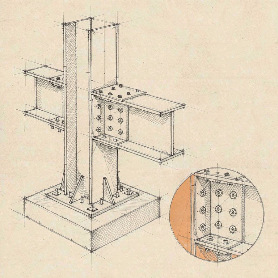
Connection design has the strongest visible effect on fit-up. Standardized hole patterns, rational edge distances, and a clear distinction between shop-fixed geometry and site-adjustable geometry are often more important than adding complexity to a joint. If both connecting parts are heavily constrained, even a small twist in one member can block assembly. If one side is detailed to accept controlled adjustment, the same level of fabrication variation may remain manageable.
End-plate connections illustrate this well. Thick plates can distort under welding, especially when the weld sequence and heat input are not matched to plate thickness and restraint. If the design assumes a perfectly flat bearing surface but the fabrication method allows bowing, bolt installation becomes difficult and contact behavior changes. Slotted holes may appear to solve alignment, yet they should be used with a clear structural purpose and directional logic. Randomly introducing slots after coordination problems emerge often shifts the problem rather than resolving it.
For bracing nodes, gusset orientation, bolt access, wrench clearance, and erection sequence matter as much as member force. A node that is compact in the model can become impractical when adjacent members arrive from different lifting directions or when bolts cannot be inserted because another plate blocks the path. Good fit-up is rarely just a tolerance issue; it is often a detailing issue hidden inside an apparently complete drawing set.
Member geometry is affected by processing route, not only nominal dimensions
Profiles cut from plate, rolled sections, built-up columns, and tapered rafters do not behave the same during fabrication. A built-up welded member may satisfy section size requirements while carrying residual sweep, camber variation, or flange offset introduced during fit-up and welding. When such members are used in repetitive frames, a small shape inconsistency can alter purlin lines, cladding support levels, and connection plane alignment over a long elevation.
Cutting method also matters. Thermal cutting can leave hardened edges, local notches, and slight angular deviation if machine calibration, consumables, or plate support are poor. Hole-making has similar consequences. Drilled holes usually offer better positional stability than holes produced under less controlled methods, particularly where multiple plies need predictable alignment. In tightly detailed moment connections or column splices, the difference between a clean datum-based process and an approximate layout process becomes visible immediately during site assembly.
Even material procurement choices can influence fit-up indirectly. Thickness variation within permitted supply range, rolling tolerances of sections, and availability of substitute profiles can alter connection detailing assumptions. If a project changes from one section series to another late in procurement, bolt stand-off, cope dimensions, or weld access can change enough to trigger site conflict unless the fabrication model is updated with discipline.
Datums and reference strategy often separate smooth erection from repeated adjustment
A workshop may have accurate machines and skilled operators, but fit-up quality still suffers if reference points change from station to station. The most reliable fabrication systems establish one governing datum for each member and carry that reference through cutting, drilling, fitting, welding, and final inspection. Problems start when a flange edge is used as the cutting reference, the web centerline becomes the drilling reference, and the finished end face becomes the assembly reference. Each step may be correct in isolation while the finished part drifts from the geometry required by the erection sequence.
This is especially important for asymmetrical members, skewed end cuts, and assemblies with mirrored left and right parts. In these conditions, a small reference error can create parts that look acceptable in the shop but do not match their intended location. Clear part marking, orientation control, and unambiguous shop drawings reduce the chance of this type of mismatch. Ambiguity is expensive once steel reaches site because field crews usually discover it at the moment a crane is occupied and a connection refuses to close.
Three-dimensional digital models can help if they are used as fabrication control tools rather than presentation models. The value lies in coordinated node geometry, clash review, and direct extraction of dimensions tied to fabrication datums. If the model is only visually correct while shop information is manually interpreted with inconsistent reference logic, digital coordination gives limited protection against fit-up problems.
Welding sequence changes final shape more than many drawing reviews acknowledge
Fabrication drawings often define the final geometry without showing how sensitive that geometry is to welding order and restraint. Distortion is not limited to visibly thin plates. Heavy assemblies can rotate, shrink, or twist when welds are concentrated on one side or when temporary restraint is released too early. This becomes critical at base plates, crane beam brackets, stiffened end plates, and built-up box or H sections.
When a design leaves almost no adjustment on site, welding procedure planning should be considered part of fit-up control. Balanced weld sequence, staged tacking, use of jigs, and intermediate verification can keep the finished assembly within a tolerance that is meaningful for erection. Without that discipline, the workshop may rely on corrective heating or mechanical forcing, which can produce a member that passes dimension checks at selected points but still carries twist or lack of squareness.
Surface treatment can also alter practical fit-up. Thick coating systems on faying or bearing surfaces, weld spatter left near contact zones, and unremoved burrs around holes may not change nominal dimensions much, yet they affect whether parts seat properly. For friction-type bolted joints, coating type and thickness need coordination with the connection design. For bearing interfaces such as column splice plates or equipment support seats, cleanliness and flatness influence how load transfers after erection.
In enclosed facilities with strict thermal performance requirements, the steel frame often has to coordinate with insulated envelope components, service penetrations, and hygienic internal finishes. A system such as Polyurethane Insulated Steel Structure Cold Chain Warehouse makes this coordination more sensitive because misalignment in the primary steel can migrate into panel joint irregularity, thermal bridge risk, door frame conflict, or drainage slope correction later in the build. The fit-up issue is no longer limited to structural assembly; it affects the entire enclosure chain.
Transport and handling can erase shop accuracy
A member fabricated accurately can still arrive in a condition that makes on-site fit-up difficult. Long slender elements may distort during loading if support points are poorly chosen. Assemblies with projecting connection plates are vulnerable to local impact. Temporary bracing added for transport can prevent movement, but if it is welded in a way that introduces restraint-related distortion or is removed without control, geometry may change again before erection.
Segmented structures are particularly sensitive. If a long truss, girder, or frame line is split for transport, the splice philosophy must reflect how the parts will be supported, lifted, and aligned on arrival. Splice location should not be decided by shipping convenience alone. A theoretically acceptable splice may become difficult to close in the field if it falls at a point of high self-weight deflection during lifting or near a node where multiple tolerances converge.
Site fit-up depends on sequencing assumptions made in design and fabrication
Drawings sometimes imply that all members are equally installable once delivered, but actual fit-up is sequence dependent. A column line erected from one fixed grid outward behaves differently from a frame assembled in modules and then connected bay by bay. If the design depends on precise geometry at a later-stage node, earlier-stage members must preserve that geometry during temporary conditions. Connection choice should reflect whether the structure will be stabilized immediately or after several pieces are in place.
Common field friction comes from pieces that are individually correct but incompatible with the chosen erection order. A brace that can only be installed before cladding rails, a stair support that blocks bolt tightening at a main connection, or roof steel that requires impossible simultaneous alignment across two grid lines are all design-fabrication coordination issues expressed as fit-up delays. These are easier to detect when erection logic is reviewed during detailing rather than after fabrication release.
Misjudgments that appear small in review can have large consequences on site
None of these issues requires a dramatic design failure to cause disruption. Site fit-up is often lost through accumulated minor decisions that each looked acceptable when reviewed alone. Steel Structure Design and Fabrication should therefore be judged as a connected production system: design defines the tolerance strategy, fabrication translates it into real geometry, transport preserves or degrades it, and erection reveals whether the assumptions were coherent.
Where fit-up performance matters, the most reliable indicator is not the elegance of the model or the apparent completeness of the drawing package. It is whether dimensions, datums, welding logic, connection adjustability, and erection sequence all point to the same physical outcome when steel is finally brought together on site.
We are more than happy to serve you here. If you have any question, please feel free to contact us.