
News center
Related Posts
Online Message
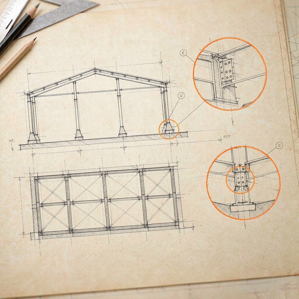
How Accurate Are Pre Engineered Steel Building Drawings
How Accurate Are Pre-Engineered Steel Building Drawings?
Pre-engineered steel building drawings can be highly accurate, but their accuracy is not automatic simply because the building is pre-engineered. It depends on whether the drawings are based on confirmed site information, coordinated structural assumptions, verified connection details, applicable design codes, and controlled fabrication data. When those inputs are complete, the drawings can guide production and erection with close dimensional coordination. When they are incomplete or changed late, even well-prepared drawings may no longer match the actual project conditions.
This question usually arises when a project is approaching fabrication or installation. A contractor may be checking anchor bolt locations, a developer may be comparing a proposal with a foundation plan, or an installer may notice that a roof opening conflicts with a service route. At that point, drawing accuracy affects more than paperwork. It can determine whether columns align with foundations, whether panels fit around openings, whether cranes can follow the erection sequence, and whether costly field modifications are avoided.
What “accurate” means in a pre-engineered steel building drawing
Accuracy has several layers. A drawing can be dimensionally correct yet still be unsuitable for fabrication if it omits a connection requirement. It can also be structurally sound but create installation problems if the foundation layout, cladding interfaces, or secondary steel details were not coordinated. In practice, accurate pre-engineered steel building drawings should agree across four related areas:
Therefore, the better question is often not “Are the drawings accurate?” but “Accurate against which confirmed inputs?” A drawing cannot reliably compensate for an unverified soil level, an outdated architectural layout, or a foundation poured from an earlier revision.
Why drawings sometimes appear accurate in the office but fail on site
Most serious mismatches do not come from a single incorrect dimension. They result from information moving between different parties without a disciplined revision process. A steel designer may issue a foundation reaction plan based on one column grid, while the civil team uses a revised grid. Later, a door opening is shifted to improve traffic flow, but the change is not reflected in the wall framing drawing. Each document can look internally reasonable, yet the assembled building will have a conflict.
Another frequent issue is the difference between design drawings and shop drawings. Design drawings establish the structural concept and design intent. Shop drawings convert that intent into fabricable components. During this conversion, connection geometry, member orientation, bolt access, splice positions, and tolerances become critical. A general arrangement drawing may show a portal frame in the correct position, but it does not necessarily confirm every plate, hole, stiffener, or erection detail required in the workshop.
Field conditions also matter. Steel frames are manufactured to controlled dimensions, while foundations are constructed on site and may have practical placement tolerances. If anchor bolts are out of position, columns may not seat properly even when the steel drawing is correct. The appropriate response is not to enlarge holes or cut steel without engineering review. The team must first determine whether the deviation affects base plate bearing, bolt edge distance, load transfer, frame alignment, or waterproofing at the slab and wall interface.
The inputs that control drawing reliability
Confirmed building use and loading criteria
A warehouse with light roof-mounted equipment is not designed the same way as a workshop with suspended services, solar panels, heavy roof loads, crane beams, or frequent large door openings. Wind, snow, seismic conditions, collateral loads, temperature effects, and rainwater requirements can all influence member design and connection detailing.
Drawing accuracy starts with a complete design brief. If the building use changes after the frame is engineered, the existing drawings may no longer be valid. For example, adding a crane runway, a mezzanine, or heavy mechanical equipment can introduce loads that the original frame and foundations were not designed to carry. A later addition should be checked as a structural modification, not treated as a simple installation detail.
Correct site and foundation information
Foundation interface drawings deserve close attention because they connect manufactured steel with site-built concrete. The steel package should provide column locations, base plate details, anchor bolt patterns, reactions, and relevant elevations. The civil design must translate this information into suitable footings, pedestals, reinforcement, and concrete levels.
Before concrete is poured, compare the latest approved anchor bolt plan against the latest steel column schedule. Verify gridline references rather than measuring only from one edge of the building. Also confirm diagonal dimensions across the grid, because a foundation can have correct individual spacings but still be out of square. Elevation checks are equally important where the project includes sloped slabs, recessed loading areas, drainage falls, or different finished floor levels.
Clear opening and cladding requirements
Doors, windows, louvres, skylights, wall penetrations, and roof curbs affect more than the panels around them. Large openings can require jamb members, headers, additional bracing, altered purlin spacing, flashing details, or changes to rainwater paths. A rolling door may fit within a wall opening on an architectural plan but still conflict with a brace rod, a column flange, or the available headroom beneath a haunch.
When reviewing drawings, check the clear opening dimensions, not only the nominal opening size. “Clear” should account for tracks, guides, trim, weather seals, structural framing, and operating clearances. This is especially important for vehicle access, forklift routes, machinery delivery, and loading operations.
How to review drawings before fabrication begins
The most effective time to find a discrepancy is before steel is cut. Once fabrication starts, a change may affect multiple connected pieces, production sequencing, procurement, and delivery arrangements. The review should focus on interfaces and decisions that cannot be easily corrected later.
Dimensional tolerances: precision is not the same as zero variation
Steel building drawings should be precise, but construction still involves tolerances. Fabrication tolerances govern how closely members, holes, plates, and assemblies must match specified dimensions. Erection tolerances govern acceptable variation in the installed frame, including plumbness, line, level, and alignment. Concrete work has its own tolerance considerations.
Problems arise when teams assume that every field condition must match the drawing with no variation at all, or when they take the opposite view and treat any mismatch as acceptable. Neither approach is reliable. The relevant question is whether the measured deviation remains within the project’s specified tolerances and whether it affects structural performance, fit-up, cladding alignment, door operation, or service installation.
Warning signs that should stop fabrication or erection
Not every question requires redesign, but certain conditions should be clarified before work continues. One warning sign is a difference between the general arrangement drawing and the anchor bolt plan. Another is an opening shown on architectural drawings but absent from wall framing or panel details. Missing bracing information, unidentified member marks, unclear bolt grades, inconsistent elevations, and connection details that do not show adequate installation access also require resolution.
During erection, stop and verify rather than forcing a fit when bolt holes do not align, a member mark does not match the drawing, a column base does not seat evenly, or a brace appears to interfere with an opening. Site modification without approval can reduce capacity, compromise corrosion protection, alter connection behavior, or create a later inspection issue. The correct path is to document the actual condition, identify the drawing revision in use, take measured dimensions, and obtain direction from the responsible engineering party.
How factory controls improve, but do not replace, drawing coordination
Controlled fabrication can reduce production errors through material identification, cutting control, hole-making procedures, fit-up checks, welding inspection, and marking systems. These measures help ensure that fabricated components correspond to approved shop information. They do not correct an inaccurate project input. A perfectly fabricated column will still be in the wrong place if the approved gridline is wrong, and a correctly drilled base plate cannot solve an incorrectly set anchor bolt group.
For this reason, approval should not be treated as a routine signature. It is the point at which the project team confirms that the steel building package reflects the intended building, the foundation interface, and the installation requirements. The more carefully that coordination is completed before fabrication, the more dependable the drawings become in the field.
Frequently asked questions
Are pre-engineered steel building drawings more accurate than conventional steel drawings?
They can be equally precise when the design information, detailing process, and quality controls are sound. Pre-engineered systems often benefit from standardized component logic and repeatable detailing, but accuracy still depends on project-specific loads, dimensions, openings, foundations, and approved revisions.
Can a contractor build from approval drawings alone?
Approval drawings are useful for confirming the general arrangement and key interfaces, but erection and fabrication normally require the complete approved drawing package, including relevant anchor bolt plans, erection details, connection information, member identification, and revision records. The exact document requirements should be established in the project scope.
What should be checked first when steel does not fit the foundation?
Confirm that the installed steel member and drawing revision are correct, then survey the actual anchor bolt locations, foundation elevations, and grid dimensions. Compare those measurements with the approved base plate and anchor bolt details. Do not alter holes, bolts, or base plates until the deviation has been evaluated.
Do shop drawings need to show every weld and bolt?
They should provide sufficient information for fabrication and erection, including applicable weld requirements, bolt sizes or grades, connection geometry, and member identification. Some standardized details may refer to approved schedules or typical connection notes, but the information must still be clear enough to avoid interpretation on the shop floor or at the site.
We are more than happy to serve you here. If you have any question, please feel free to contact us.