
News center
Related Posts
Online Message
Steel Building Design for Coastal Wind Loads
What wind loads mean for steel building design in coastal areas
At a coastal site, a steel warehouse can appear straightforward during early layout review: clear span, eave height, dock doors, roof drainage, and column grid. Then the wind study arrives. A building near open water may face higher mean wind exposure, sharper pressure peaks at roof edges, stronger suction around large openings, and wind-driven rain that tests every cladding joint. These effects do not only increase the size of a few frame members. They can change the governing load path from roof sheet to purlin, purlin to rafter, rafter to column, column to foundation, and foundation to soil.
For coastal Steel Building Design, the essential judgment is that wind must be treated as a system-level action rather than a single roof-load figure. A credible design starts with the governing local wind standard and site data, then checks exposure, topography, building geometry, enclosure classification, pressure zones, load combinations, serviceability, and corrosion protection together. A frame that satisfies a simplified overall wind calculation may still have vulnerable edge cladding, under-designed fasteners, unstable secondary steelwork, or connections that cannot transfer uplift forces reliably.
Why coastal wind changes the design basis
Wind speed increases with height above ground and is strongly affected by surrounding terrain. Inland industrial areas with dense buildings and mature vegetation can provide a degree of shielding. A logistics facility on a reclaimed shoreline, port estate, open coastal plain, or low-lying industrial zone may have little effective shielding. The wind approaches the building across long, unobstructed fetches and produces a more severe exposure condition.
Technical evaluators should distinguish between the basic wind climate and the site-adjusted wind action. The applicable standard establishes the starting wind speed or velocity pressure using the jurisdictional wind region, return period, risk category, and other code-defined parameters. That starting point is then modified for the actual site and building. Exposure category, terrain height, escarpments, ridges, nearby structures, building height, and plan dimensions all influence the pressure used for design.
Wind loading is also directional. A rectangular building might have a different projected area, internal pressure condition, and bracing response when wind acts on the gable end rather than the long elevation. A coastal facility should not be reviewed on the assumption that the “usual” wind direction governs every component. Seasonal storms, typhoon-prone conditions where applicable, and local directional wind maps can make another direction controlling for frames, roof zones, canopies, or wall panels.
Start with the site information that can alter the result
Before accepting preliminary member sizes, confirm that the wind-design inputs are traceable to the actual location. A postal-area description or a generic “coastal” label is not sufficient. The design team needs a precise site location, the governing code edition, building use or importance classification, elevation data, surrounding terrain description, and information about topographic features.
Wind studies are sometimes reduced to one design pressure supplied early in a project. That can be useful for feasibility estimates, but it is not enough for final detailing. External pressure coefficients vary across a roof and wall surface. The field zone often carries lower suction than corners and edge strips, while roof overhangs, parapets, and abrupt level changes can produce concentrated uplift demands. A single uniform pressure may conceal the components that fail first in severe weather.
The load path is more important than the headline wind speed
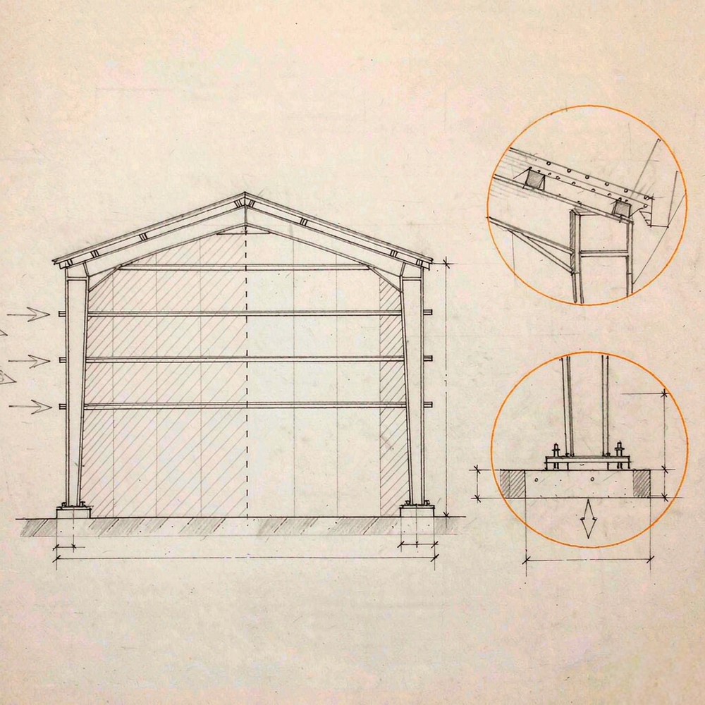
Wind pushes on one face of the building, pulls on roof and leeward surfaces, and creates forces that must travel through all connected elements without interruption. Reviewing only the primary portal frame leaves important gaps. The roof sheeting, sidelap and seam fasteners, purlins, sag rods or bridging, eave struts, wall girts, bracing, frame joints, base plates, anchor rods, and foundations may each see different combinations of shear, axial force, bending, and uplift.
Consider a portal-frame distribution building with a wide clear span. The roof frame may resist transverse wind in its plane, preserving open internal space without bracing across operational areas. But longitudinal wind needs its own defined resistance system, often through vertical bracing bays, rigid frames, diaphragm action where permitted by the governing design method, or a combination of these. The engineer must identify how wind reaches the longitudinal bracing and whether the route is interrupted by dock openings, large shutters, mezzanines, or façade changes.
Connection review deserves particular attention in coastal projects because wind often governs tension rather than member strength. A rafter-to-column joint can be adequate under gravity loading but require different bolt group capacity under frame uplift and sway. Base connections must transfer overturning-induced tension into anchor rods and concrete. Purlin cleats, girt connections, bracing gussets, and canopy supports need forces derived from the final analysis rather than from nominal member capacities.
Roof uplift is rarely uniform
Roof corners and perimeter strips are repeatedly critical because flow separates around the building edges. Local negative pressure can pull roof panels upward even while the overall roof frame appears lightly loaded. The practical consequences extend to sheet thickness, fastening pattern, fastener type, purlin spacing, roof-light detailing, ridge assemblies, and penetrations for ventilation or services.
A useful review question is not merely “Are the roof panels rated for the wind?” It is “Which pressure zone applies to each panel area, and does the tested or calculated fixing arrangement match that zone?” Fastener spacing that works in the roof field may be insufficient at eaves, ridges, corners, or roof steps. The same question applies to wall cladding, particularly at building corners and around large door openings.
Openings can change the entire pressure condition
Large loading doors are a normal feature of coastal logistics buildings. During operation, several doors may be open at once, whether by traffic demand, equipment movement, or a temporary interruption in door control. If wind enters through a dominant opening, internal pressure can rise or reverse, adding to external suction on the roof and leeward wall. This is not a minor cladding issue; it can materially alter the design action on roof systems, end walls, and connections.
The enclosure classification required by the governing code should therefore reflect realistic operating conditions. Assess whether a door is normally closed during a design wind event, whether it is designed and controlled to remain closed, and whether damage to another opening could create an internal pressure path. Mechanical smoke vents, louvres, personnel doors, wall penetrations, and damaged cladding scenarios may also affect the assessment where the applicable standard requires them to be considered.
Dock canopies require a separate look. A canopy can experience uplift on its upper surface and positive pressure beneath it, creating a demanding net upward force. The support members, cantilever root, purlin connections, fascia, tie-in to the main building, and anchorages must all be designed for that pressure pattern. Treating a canopy as an architectural appendage after the main frame is completed can result in difficult strengthening work.
Frame stability must be checked in both directions
Portal frames are efficient for transverse resistance, but their behavior depends on geometry, haunches, member slenderness, joint rigidity, roof restraint, and the assumed continuity of secondary members. Wind acting normal to the sidewall causes lateral sway and may produce uplift at one column base while increasing compression at the other. The analysis should include the appropriate second-order effects when required, because frame deflection can increase internal moments and alter stability margins.
Along the building length, braced bays must be placed where they can function without conflicting with circulation, dock operations, fire access, conveyor routes, or future expansion joints. A common coordination problem occurs when a structural bracing line is placed in a wall bay later needed for a loading door. Relocating the brace is possible, but it changes collector forces in eave members and roof bracing. The revised load path should be rechecked rather than treated as a drafting change.
For facilities built around high pallet turnover, the structural grid is usually coordinated with racking and traffic movement. In a Steel Logistics and Distribution Center, a clear span of 24–48 m and bay spacing of 8, 9, or 10 m may support internal logistics planning, but the grid should still be tested against wind-bracing requirements. The most economical steel grid is not automatically the most practical arrangement once end-wall openings, dock lines, rack modules, and bracing locations are considered together.
Serviceability affects enclosure performance and operations
Strength design prevents collapse or loss of load-carrying capacity under prescribed combinations. Serviceability addresses a different question: will the building remain usable and weather-tight under more frequent wind conditions? Excessive frame drift can stress cladding interfaces, distort doors, affect flashing, and cause recurring sealant or fastener problems. Roof purlin deflection can create ponding tendencies where drainage falls are limited, especially when construction tolerances and roof penetrations are added to the geometry.
Deflection limits should be taken from the governing standard, project specification, cladding supplier requirements, and functional needs rather than applying one generic limit to all elements. A wall with tall insulated panels, glazing, or closely controlled dock equipment may require tighter movement control than an open-sided shelter. Rolling doors and sectional dock doors need adequate structural clearance and jamb stiffness; otherwise, small movements during high winds can lead to poor operation or damage.
Wind-driven rain is a related serviceability issue. It does not usually change the primary frame analysis, but it exposes weaknesses in laps, flashings, sealants, closures, eave details, and interfaces around openings. Coastal projects should coordinate roof drainage, overflow paths, gutters, downpipes, and sealed penetrations early. Corrosion damage accelerates when water is trapped in poorly drained crevices or between incompatible materials.
Corrosion protection is part of wind reliability
Salt-laden air affects the durability of steel members, fasteners, cladding, coatings, and connections. Over time, corrosion can reduce section thickness, compromise fastener performance, and make maintenance access more difficult. Wind design and corrosion design are connected because the parts most exposed to uplift and cyclic movement—roof fixings, edge flashings, canopy connections, external bracing, and base details—are often also exposed to moisture and salt deposition.
The coating system should be selected for the local corrosivity category and the project maintenance strategy. Options may include properly prepared painted systems with an epoxy zinc-rich primer, hot-dip galvanizing, or duplex protection combining galvanizing with a paint topcoat. The selection is not just a material preference. It must consider expected exposure, abrasion, welding and repair areas, bolted interfaces, drainage, inspection access, and compatibility with roof and wall components.
Detailing often determines whether a specified coating can perform as intended. Avoid water traps at base plates and stiffeners, unsealed lap gaps that hold salt deposits, inaccessible crevices, and horizontal surfaces with poor drainage. Provide sensible separation where dissimilar metals could create galvanic concerns. Fastener materials and coating compatibility should be checked alongside the cladding system rather than selected independently.
A practical technical review before fabrication
Fabrication should begin only after the wind criteria have been converted into coordinated structural and enclosure documents. The following review sequence helps identify issues while changes are still manageable:
For prefabricated buildings, this coordination needs to survive the transition from calculation to fabrication. CNC-cut parts, welded assemblies, and Tekla-based shop models can support consistency, but only if the approved design data define the controlling wind zones and connection requirements clearly. Material traceability, weld inspection, and inspection records are useful quality controls; they do not replace a correct site-specific wind design.
Where reviews often go wrong
One recurring error is treating coastal exposure as a simple percentage increase over an inland design. That shortcut can overlook topography, directional effects, enclosure classification, and local component pressures. Another is checking the main steel frame without obtaining the cladding supplier’s pressure and fixing data for the actual panel span and pressure zone.
It is also risky to assume that a strong primary frame compensates for flexible secondary members or weak enclosure fixings. Wind damage often begins at edges, penetrations, doors, gutters, canopies, and local connections. Once the building envelope is breached, internal pressure may increase and transfer larger demand to components that were not intended to act under that condition.
Where a project uses a Steel Logistics and Distribution Center configuration with 9–15 m eave heights, wide dock openings, and a 6 m cantilever canopy, the wind review should explicitly separate the main portal frame from dock-area attachments and opening reinforcements. Header beams and jambs may need to address both local impact-related functional demands and wind-driven reactions from adjacent façade and canopy elements.
The final acceptance question is therefore not whether the building has been “designed for wind” in general terms. It is whether the approved calculations, drawings, cladding schedules, connection details, and corrosion provisions all use the same coastal design assumptions. When those documents align, the structure has a defined path for resisting severe wind rather than relying on isolated conservative-looking components.
We are more than happy to serve you here. If you have any question, please feel free to contact us.