
News center
Related Posts
- ▶ Prefab vs. Conventional Warehouse Construction: Comparing Timelines
- ▶ Planning a Prefab Warehouse: Clear Span, Height and Loading Bays
- ▶ How Long Does It Take to Build a Commercial Steel Building?
Online Message
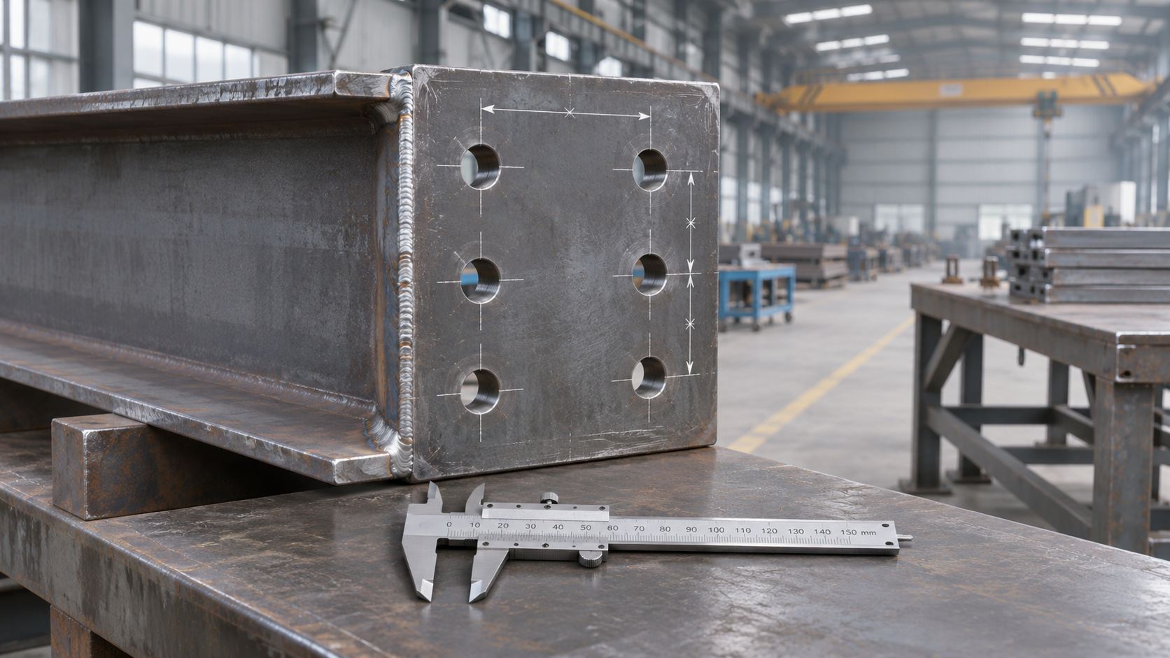
The acceptable tolerance for a structural steel component is the deviation permitted by the governing project documents and the applicable standard for that particular feature. There is no single value that applies to every beam, column, bolt hole, and erected frame. Member length, straightness, hole location, and column plumbness are controlled separately, often with different reference points and measurement methods.
This distinction matters when a prefabricated frame reaches the site and the bolt holes do not line up or a beam will not fit between supports. A component can be close to its nominal dimensions and still cause a connection problem. To decide what tolerance is acceptable for structural steel components, first identify the controlling requirement, then measure the feature in the specified way and assess its effect on the assembly.
Start with the applicable documents, not a universal number
Structural steel tolerances may be established by a combination of the contract, structural drawings, project specifications, fabrication requirements, and erection requirements. Common references include the AISC Code of Standard Practice in the United States, EN 1090-2 in Europe, and AS/NZS 5131 in Australia and New Zealand. The applicable edition and any project-specific modifications matter.
These documents do not all use the same categories or measurement rules. A value taken from one standard should not be transferred to a project governed by another without checking its scope and conditions. Project documents may also specify tighter limits for features that affect equipment, cladding, crane rails, or interfaces with other trades.
Before fabrication begins, establish the following:
- Which standard and edition govern fabrication and erection.
- Whether the drawings or contract impose stricter requirements for particular members or connections.
- Which dimensions are measured in the shop and which are verified after erection.
- The reference points, measurement conditions, and acceptance method for critical features.
- Who has authority to resolve conflicts between the drawings and the referenced standards.
Do not assume that a general note such as “fabricate to standard tolerances” answers every question. A connection with limited adjustment may need an explicit dimensional requirement, even when the rest of the frame can use the ordinary provisions of the governing standard.
Fabrication tolerances: which dimensions control fit?
Fabrication tolerances cover the geometry of individual pieces and assembled shop components. The relevant limit depends not only on the feature but sometimes also on member length, end preparation, connection type, or whether the member is intended to bear against another surface.
Length is only one part of a connection
Consider a beam with end plates at both ends. An acceptable overall length does not necessarily mean it will bolt into place: one plate may be slightly rotated, or a hole group may be displaced relative to the beam centerline. Checking only the end-to-end dimension leaves those errors undiscovered.
For a critical connection, inspect the dimensions as a group. Establish the beam datum, verify the position of each end plate, and measure the hole pattern from the reference used on the approved shop drawing. Where the connection has slotted holes or other adjustment, confirm their orientation and intended purpose. The presence of a slot does not make every misalignment acceptable.
Separate mill tolerances from fabrication tolerances
Rolled sections arrive with permissible variations in their as-produced dimensions and shape. Cutting, drilling, welding, and assembling add other dimensional considerations. The material product standard and the project’s fabrication standard may therefore govern different characteristics of the same member.
For example, a rolled section’s flange geometry is not necessarily judged by the same rule as the location of a plate welded to it. Inspectors should identify which requirement applies to the measured feature rather than treating every deviation as a fabrication error.
Shop accuracy does not replace erection control
Erection tolerances address the position and alignment of steel in the completed frame. A column may be fabricated within tolerance but installed out of plumb; conversely, the erected frame may be aligned even though an individual component requires a documented fabrication review.
Typical field checks include column location and plumbness, beam elevation, alignment of connection points, and the position of the frame relative to established building grids. The governing erection provisions define how these checks are made and which conditions apply. Measurements taken before the frame is sufficiently connected, braced, or adjusted may not represent its final condition.
Anchor bolts and foundations deserve early attention because they form an interface between different scopes of work. Their permitted deviations may be set by requirements separate from those for steel fabrication. Survey the as-built anchor locations and elevations against the approved setting-out information before the steel arrives or before erection proceeds at the affected location. Do not assume that an oversized base-plate hole can accommodate every error: available clearance, washer details, and structural requirements all matter.
Concrete surfaces, grout allowances, shims, and base-plate elevations should also be checked against the design details. A frame cannot be assessed accurately by looking at steel dimensions alone when its supports or survey control are in question.
Allow for the effect of several small deviations
Individual features can each comply with their own limits while their combined position leaves little room for assembly. A column location, beam length, end-plate position, and hole-group location may all influence the same connection. Their deviations do not necessarily cancel each other out.
Before releasing a critical detail, compare the possible movement at the interface with the adjustment actually available. Identify the fixed points first, then consider which dimensions can vary and in which direction. The review should use the limits and measurement definitions applicable to the project; simply adding unrelated tolerance values without considering their direction or reference points can give a misleading result.
This is especially useful where steel connects to precast concrete, equipment supports, existing structures, or closely spaced adjacent frames. Those interfaces often involve different contractors, measurement systems, or work sequences. Agreeing on a common datum and exchanging as-built measurements can be more valuable than tightening every fabrication dimension.
Measure the feature the same way the requirement defines it
A tolerance comparison is meaningful only when the measured value and the acceptance limit refer to the same thing. A straightness check, for example, needs the specified reference line and measurement locations. A length check needs clearly identified ends. A hole-location check needs a datum rather than an estimate from an irregular plate edge.
- Identify the requirement. Record the drawing revision, standard, feature, and applicable limit before measuring.
- Establish the reference. Use the specified grid, centerline, end surface, or other datum. Confirm that the datum itself is suitable and accessible.
- Select an appropriate instrument. A tape, straightedge, level, survey instrument, or calibrated gauge may be suitable depending on the feature and required accuracy.
- Record the result and conditions. Note where and how the measurement was taken, including support or loading conditions when they affect the result.
- Compare like with like. Check the reading against the correct limit and retain the inspection record where required by the project.
Temperature, member support, sag, surface condition, and access can influence readings, particularly on long members or when a tight limit is specified. If two measurements disagree, repeat them from the same datum with a suitable instrument before deciding that the component is nonconforming. Do not average inconsistent readings simply to obtain a passing result.
When a dimension is outside tolerance
First, identify and record the affected piece or location, the measured deviation, the relevant requirement, and the measurement method. Check whether the drawing revision and reference points are correct. A perceived mismatch can result from measuring the wrong face, using an outdated drawing, or comparing shop dimensions with an erection requirement.
If the deviation is confirmed, assess the connection and surrounding assembly before attempting a correction. Possible dispositions include rework, an engineered modification, or acceptance through the project’s formal deviation process. The appropriate route depends on structural effects, connection geometry, and the governing documents.
Do not enlarge holes, cut a member, force a connection into place, or add unapproved welds merely to make the parts fit. Such changes can affect edge distance, bolt behavior, member capacity, protective coatings, or erection stability. Proposed structural changes and acceptance of nonconforming work should go through the designated engineer and approval process.
Where a repeated deviation appears across several pieces, inspect the common process as well as the individual components. A misplaced fabrication datum, incorrect shop drawing, unsuitable jig, or survey-control error can produce a recurring fit-up problem. Correcting only the first visible mismatch may leave the rest of the assembly affected.
Put critical tolerances into the fabrication package
When ordering prefabricated steel, provide the governing standard and edition, approved structural drawings, connection details, and any project-specific limits. Identify interfaces that have little adjustment, including embedded items and connections to work supplied by others. Make clear whether dimensions refer to finished assemblies, individual pieces, or the erected frame.
Request inspection records for the features that matter to fit-up, rather than a generic statement that all dimensions are acceptable. For a critical interface, the record should show the measured feature, its datum, the applicable acceptance criterion, and the result. Agree in advance on how nonconformities will be reported and who can approve a repair or deviation.
The practical acceptance question is therefore not whether a steel component is “close enough” in isolation. It is whether each relevant feature meets its governing requirement, measured from the correct reference, and whether the connection has been detailed to accommodate the permitted variation of the adjoining work.
We are more than happy to serve you here. If you have any question, please feel free to contact us.