
Related Posts
- ▶ Prefab vs. Conventional Warehouse Construction: Comparing Timelines
- ▶ Planning a Prefab Warehouse: Clear Span, Height and Loading Bays
- ▶ How Long Does It Take to Build a Commercial Steel Building?
Online Message
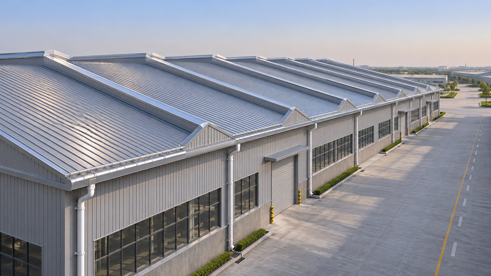
The main roof design options for a multi-span steel building are a single gable spanning the overall building width, a single-slope roof, and a multi-gable roof with repeated ridges and valleys. The best choice depends less on appearance than on where water must drain, how much height the building needs, and whether interior columns are acceptable.
A multi-span building has a structural frame divided into two or more spans, typically with interior columns supporting rafters or beams. Its roof shape does not have to follow those spans: several structural spans can sit beneath one broad gable, while a multi-gable roof can place ridges and valleys over a repeated frame layout. Keeping that distinction clear prevents roof geometry from being confused with the structural system.
Single gable over multiple structural spans
A single-gable roof has one ridge, with roof planes sloping toward opposite sides of the building. The frame beneath it can still contain intermediate columns. This arrangement avoids internal roof valleys and directs rainwater toward the outer eaves, where gutters and downpipes are generally easier to inspect and maintain than drainage buried within the roof footprint.
The trade-off is geometry. As the overall building width increases, a fixed roof pitch produces a greater difference in height between the eaves and ridge. For a very wide building, that can raise the ridge above planning limits or create more enclosed volume than the operation needs. Lowering the pitch reduces the height, but it also changes drainage performance and may narrow the choice of roof panels and seam details.
A single broad gable is worth considering where the site has accessible drainage along both sides and the required ridge height is acceptable. It can suit a warehouse or production hall that needs a straightforward roof profile without internal gutters. It is less attractive when height restrictions are severe or when the long roof slopes create difficult panel-length and drainage requirements.
Interior columns also deserve separate attention. A gable roof does not automatically provide clear space beneath the entire roof. Column positions must be coordinated with storage aisles, machinery, vehicle routes, and any future changes to the floor layout.
Single-slope roof: simple direction, growing height difference
A single-slope, or mono-pitch, roof falls in one direction across the building. It can direct runoff to one side, which is useful when site drainage, access, or an adjoining structure makes that side preferable. The high and low sides also create opportunities for high-level windows or ventilation openings, subject to weather protection and the overall ventilation design.
The main limitation is the height difference across the full width. For example, a roof falling at 1:20 across 40 metres has a two-metre elevation difference before allowing for structural depth and other details. That difference affects wall height, cladding area, interior volume, and potentially planning approval. The figure illustrates geometry only; the actual minimum slope must be established from the selected roof system, climate, drainage design, and applicable requirements.
A single-slope roof is therefore easier to justify over a narrower building width or where the high side is useful for operational clearance. On a wide footprint, the design team may need to compare the extra wall and frame cost against the benefit of collecting water on one side. A shallow slope should not be chosen solely to reduce wall height: panel profile, seam treatment, roof penetrations, and the ability to drain after deflection all matter.
Directing all runoff to one edge also concentrates the drainage demand there. The gutter, downpipes, underground system, and discharge point must be sized as a connected system rather than treated as an afterthought.
Multi-gable roofs: lower individual rises, more valleys
A multi-gable roof repeats a series of ridges and valleys across the building. Each individual roof slope covers less horizontal distance than a single gable over the full width. At the same pitch, that can keep each ridge rise lower and make the roof profile more manageable on a wide building.
This geometry can work well with a repeated structural grid, but the roof valleys introduce a significant design obligation. Water from two adjacent slopes is collected at each valley and carried toward outlets. Those gutters must have sufficient capacity, suitable falls, accessible outlets, and a safe overflow path. Their detailing also needs to accommodate movement between roof components and prevent leakage at joints, penetrations, and connections.
The drainage arrangement should be established early. A valley may discharge toward the building ends, toward downpipes at selected points, or into another engineered drainage route. Each approach affects gutter length, outlet spacing, structural coordination, and maintenance access. A design that looks economical in frame weight can lose that advantage if it requires complex gutters, internal downpipes, or difficult installation details.
Snow and ice require particular care. Valleys and adjacent roof areas can experience accumulation or drifting that differs from the load on an unobstructed roof plane. The structural engineer must use the applicable site-specific loading rules rather than assume that every bay carries the same snow load. In cold conditions, the drainage concept must also account for ice formation and the consequences of blocked outlets.
Multi-gable roofs are often a strong candidate when a wide building cannot accommodate the ridge height of a single gable. Their suitability depends on whether the project can provide robust valley drainage and a practical maintenance route throughout the building’s life.
How the options compare
Roof pitch is a system decision, not just an angle
Pitch changes more than the outline of the building. It affects runoff speed, ridge height, roof surface area, cladding compatibility, and the detailing needed at laps and penetrations. A steeper roof can improve drainage geometry, but it may increase building height and change wind effects. A lower pitch can reduce the rise of a wide roof, yet it places greater importance on the selected panel system and the quality of joints and penetrations.
There is no universal pitch that makes every steel roof watertight. Minimum permitted slopes depend on the roof covering and its installation details, including whether sheets are continuous or have end laps, how seams are formed, and how the manufacturer specifies the system. The project engineer must also consider the site’s rainfall, snow, wind, and applicable code requirements.
Deflection is another reason to look beyond the nominal drawing. Rafters, purlins, decking, and gutters move under load. On low-slope areas, that movement can reduce effective drainage fall or create local depressions. The design needs to consider the roof in its loaded condition, not merely as a perfect plane before cladding and equipment are installed.
Drainage choices can determine the roof choice
Two configurations with similar structural costs can have very different water-management requirements. A single gable generally sends water to exterior eaves; a multi-gable roof collects part of it at internal valleys. Neither arrangement is automatically safe without an adequate outlet and overflow strategy.
For any option, drainage design should account for the contributing roof area, design rainfall, gutter geometry, outlet capacity, and downstream restrictions. Where a blocked outlet could allow water to accumulate against roof or wall elements, overflow provision is especially important. The consequences of blockage should be considered at the concept stage, when gutter locations and building elevations can still be changed.
Access matters as much as capacity. A valley gutter hidden between tall roof slopes may be harder to inspect and clear than an external eave gutter. Leaves, packaging debris, ice, or other obstructions can affect performance, so the design should provide safe access for inspection and cleaning without relying on personnel walking across fragile or unsuitable roof areas.
Daylight and ventilation depend on openings, not roof shape alone
Each roof form can incorporate daylight or ventilation, but the position of openings changes the detailing. A gable roof may accommodate ridge ventilation or openings in end walls. A single-slope roof can offer a high wall for windows or exhaust openings. A multi-gable arrangement creates repeated ridge lines that may be used for ventilators or other features, provided the structural and weatherproofing details are designed for them.
A raised roof monitor is another possible feature: an elevated section above part of the roof can provide space for vertical glazing or ventilation openings. It is an addition to a roof configuration rather than a replacement for the primary structural layout. Its benefits must be weighed against extra framing, flashing, wind exposure, and the need to control rain entry.
Rooflights can reduce daytime lighting demand, but their placement affects heat gain, glare, insulation continuity, and maintenance. They also introduce penetrations or changes in roofing material that require compatible support and weatherproofing. Where the building contains heat-producing equipment, ventilation openings should be located according to the intended airflow path; a ridge opening alone does not guarantee adequate ventilation.
Coordinate the roof with structure, equipment, and installation
Roof shape does not determine whether the frame is efficient on its own. Span lengths, bay spacing along the building, column positions, bracing, crane loads, wind uplift, and local ground conditions all influence member sizes and foundations. A lighter-looking roof arrangement can transfer different forces to columns and foundations, so options should be compared as complete structural schemes.
Future rooftop equipment needs attention before the frame is finalized. Solar panels, ventilation units, pipework, and maintenance walkways add loads and may restrict access to gutters or rooflights. Their attachment methods affect purlin design, roof penetrations, and the roofing warranty conditions. An allowance described only as “future solar” is less useful than an agreed loading, coverage area, and proposed fixing strategy.
Manufacturing and transport also shape the practical solution. Long roof sheets may reduce the number of end laps, but their length can be constrained by production, shipping, handling, and installation access. If sheets must be lapped, the lap arrangement has to suit the roof pitch and selected system. Repeated multi-gable bays may simplify component repetition, while adding valley flashings and gutter work; neither outcome should be assumed without a detailed scope comparison.
For imported steel packages, the design responsibility needs to be explicit. The purchaser, structural designer, steel supplier, roof-system supplier, and installer should know which party is responsible for frame calculations, connection design, cladding support, gutter sizing, and compatibility with local requirements. Material or factory certifications do not by themselves establish that the completed building design complies with the rules at the project site.
A useful comparison starts with the same building footprint, required internal clearances, column restrictions, design loads, roof covering, and drainage criteria for each option. Compare the complete installed scope—including walls, flashings, gutters, outlets, and access provisions—not just the primary steel tonnage. The preferred roof is the one that meets the operating and site constraints without transferring an overlooked cost or maintenance problem to another part of the building.
We are more than happy to serve you here. If you have any question, please feel free to contact us.