
News center
Related Posts
- ▶ Prefab vs. Conventional Warehouse Construction: Comparing Timelines
- ▶ Planning a Prefab Warehouse: Clear Span, Height and Loading Bays
- ▶ How Long Does It Take to Build a Commercial Steel Building?
Online Message
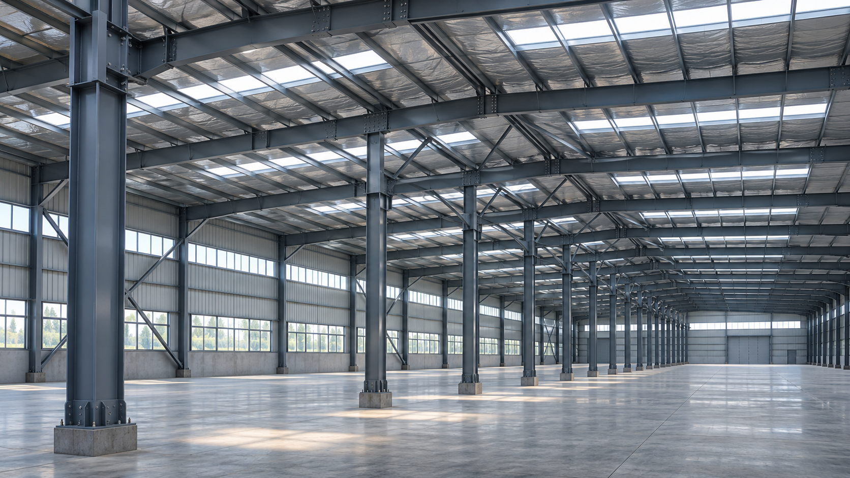
There is no single maximum span for a multi-span steel building. A building can cover a very large overall width by adding internal column lines and roof spans, but the maximum practical width of each individual span depends on the frame system, loads, site conditions, and acceptable cost. A proposed building may be structurally feasible yet uneconomical or poorly suited to the operations inside it.
For an owner planning a factory or warehouse, the first decision is therefore how much uninterrupted space is needed between columns. Once that is clear, an engineer can compare column layouts and structural systems against the building’s overall width, operating requirements, and local design rules.
Which span are you trying to maximize?
The word “span” can describe different dimensions in a steel building. Confusing them can lead to a misleading answer about the maximum size.
- Individual span: the distance between adjacent supports across the building, such as an exterior column and an internal column, or two internal column lines.
- Overall building width: the full distance across all spans. It includes the spaces between every column line.
- Bay spacing: the distance between successive frames along the length of the building. Bay spacing is a separate dimension that also affects the roof structure and the loads carried by each frame.
For example, a building with three spans of 24 meters has a nominal overall width of 72 meters. That does not mean it has a 72-meter clear span: internal columns divide the width into three supported sections. The spans also do not have to be equal. Their dimensions can be adjusted to suit production lines, storage areas, or access routes, provided the structure and foundations are designed for the resulting loads.
In general, adding spans can increase total building width without requiring every roof member to cross that entire width unsupported. The practical limit on total width then becomes a project-specific question involving the number of column lines, roof drainage, expansion considerations, foundations, construction logistics, and the way the building must operate.
How wide can each individual span be?
There is no reliable universal maximum that applies to every multi-span steel building. Steel frames can be designed for wide spaces, but the span that makes sense for a particular project depends on more than the strength of the steel. The frame must also control deflection and stability under the required load combinations, connect safely to its supports, and remain practical to fabricate and erect.
As an individual span grows, the primary roof members generally need greater structural capacity. That may require deeper sections, additional steel, a truss, or a different frame arrangement. Connections and foundations may also change. The resulting cost does not increase in a simple, fixed proportion to the span, because the entire load path and frame geometry influence the design.
A larger span can still be the better choice when an internal column would interrupt a production process, block vehicle movements, or restrict storage. The useful comparison is between complete building layouts: the extra structural and foundation work needed to remove a column versus the operational value of the space gained.
Frame type changes the answer
A multi-span building may use portal frames, trusses, or other engineered systems. A portal frame can provide an efficient arrangement for many buildings, while a truss may be considered where a wider span or different roof geometry justifies the extra fabrication and connections. The best choice depends on the full design, including available headroom and construction constraints.
Member depth matters operationally. If a wider span requires a deeper roof structure, the building may need a higher overall roof to preserve the same clear height below it. That can affect cladding area, wind exposure, erection requirements, and cost. A span comparison that holds only the floor area constant can miss these consequences.
What determines the practical maximum?
Two buildings with the same plan dimensions can need substantially different structures. Before treating a span as achievable for a new project, establish the conditions under which it was designed.
Roof loads and local conditions
The roof must carry its own weight and the applicable imposed loads. Depending on the project, these can include snow, wind, maintenance access, suspended services, solar equipment, and other permanent or temporary loads. Seismic requirements may also affect the structural system and its connections.
Loads are determined for the site and the applicable design rules; they should not be borrowed from a building in another location. A wider span that works under lighter roof loading may need a different frame or additional support under heavier loading. Wind uplift can also govern parts of the design, including connections and foundations, even when gravity loads appear manageable.
Future equipment deserves attention at this stage. If solar panels, suspended pipes, conveyors, or other services may be added later, their intended locations and loads should be included in the design brief. A roof sized only for the initial installation may not have the capacity or connection details needed for later additions.
Bay spacing and the roof system
Increasing the spacing between frames along the building length can reduce the number of main frames, but it also changes the area of roof supported by each frame. Purlins and roof sheeting must span the selected bay spacing, and the main frames must carry the loads delivered to them.
For that reason, the widest possible transverse span and the widest possible bay spacing should not be selected independently. A layout that saves steel in one part of the building may add it elsewhere. Engineers normally evaluate the primary frames, secondary members, roof covering, and connections together.
Height, cranes, and operational loads
A tall building or one fitted with overhead cranes introduces design demands that cannot be judged from roof span alone. Crane loads act on the supporting structure and foundations, while crane movement can impose horizontal forces and serviceability requirements. The crane capacity, runway arrangement, lift height, and operating conditions need to be defined before the frame and column layout are settled.
Even without cranes, the required clear height can influence the design. Columns, braces, haunches, roof members, and suspended services all occupy space. A stated eave height or overall building height does not by itself establish the usable height throughout the building.
Deflection, drainage, and foundations
A roof can be strong enough to resist its design loads and still move more than the project can tolerate. Excessive deflection may affect cladding, gutters, suspended equipment, or the building’s appearance. The allowable movement depends on the applicable rules and on the materials and equipment attached to the structure.
Drainage also becomes more important as the roof plan grows. In a multi-span arrangement, internal valleys or gutters may be required, depending on the roof configuration. Their capacity, access for maintenance, and provision for overflow should be considered alongside the structural layout. Support locations and roof slopes need to work with the drainage design.
At ground level, internal columns transfer concentrated loads into foundations. Soil conditions and foundation design can change the economics of adding supports. Removing a column may reduce the number of footings, but the remaining foundations and steelwork may need to resist larger forces. Neither option is automatically cheaper.
When is a wider span worth the extra structure?
Start with the activities that cannot easily move. A production line with large equipment, for example, may need a broad column-free zone for installation and maintenance. A warehouse may place greater value on column positions that align with storage aisles and vehicle routes. In either case, the most useful span is the one that supports the intended layout without creating disproportionate structural demands.
Internal columns are less disruptive when their locations are coordinated with partitions, equipment boundaries, or gaps between storage blocks. They become costly to the operation when they sit inside a turning path, obstruct material flow, or prevent a planned production line from being extended. A structurally efficient grid can still be a poor business decision if it restricts the use of the floor.
Consider unequal spans where different parts of the building have different needs. A wider section can serve an area that requires open space, while narrower spans elsewhere provide support where columns are acceptable. The resulting frame must be engineered as a complete system; unequal geometry can change force distribution and connection details.
The opposite approach may also be reasonable. If equipment is flexible and columns can be placed along regular boundaries, several moderate spans may provide the required overall width with a simpler structural arrangement. The owner should compare usable floor space, clear height, foundations, roof drainage, and construction requirements across the alternatives—not just the weight or price of the main steel frame.
How to establish a span limit for a specific project
Before asking for a maximum span or comparing quotations, prepare a layout that shows the building width and length, required clear height, and areas where columns cannot be placed. Include vehicle routes, large equipment, doors, storage arrangements, and any anticipated changes to the operation. These constraints give the structural designer a reasoned starting point for the column grid.
The design brief should also identify the project location, applicable design requirements, roof covering, intended roof-mounted or suspended equipment, and any crane requirements. Site and foundation information is needed to develop the support design. If some operating loads or future expansion plans are undecided, the alternatives should be identified so their effect on the frame can be assessed.
Ask for proposed dimensions to be stated clearly: individual spans, overall width, bay spacing, and clear heights at the locations that matter. Where alternatives are being compared, they should use the same site loads and operating assumptions. Otherwise, an apparently longer or cheaper span may reflect a different scope rather than a more suitable design.
The maximum span worth specifying is reached when the next increase in column-free width no longer provides enough operational benefit to justify its effect on the structure, foundations, roof, and construction. That point is established through a project-specific design comparison, with the column grid and the intended use of the building considered together.
We are more than happy to serve you here. If you have any question, please feel free to contact us.