
News center
Related Posts
- ▶ Prefab vs. Conventional Warehouse Construction: Comparing Timelines
- ▶ Planning a Prefab Warehouse: Clear Span, Height and Loading Bays
- ▶ How Long Does It Take to Build a Commercial Steel Building?
Online Message
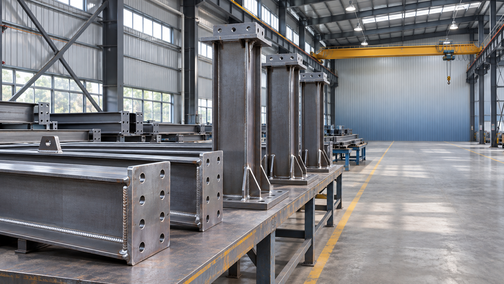
The steel structure design and fabrication workflow turns a building’s requirements into engineered members, shop drawings, manufactured components, and an installation sequence. The work moves through defined stages, but decisions often travel backward: a transport limit can change a splice location, a connection detail can affect member size, and a late equipment load can require revisions to steel already released for fabrication.
A coordinated workflow establishes the design basis first, resolves interfaces before shop production, and keeps each fabricated piece traceable to an approved drawing. Its practical value is clearest at the handoffs between stages, where an assumption that is acceptable in a calculation model must become a dimension, weld, bolt group, coating requirement, or erection instruction.
1. Establish the design basis and building geometry
The process starts with the intended building use and the conditions the structure must resist. The design basis identifies the applicable design standards, site location, building dimensions, support conditions, design life, and required performance. It also defines the loads and load combinations used in structural analysis.
Building geometry includes more than length, width, and eave height. Column spacing, roof slope, clear openings, internal obstructions, and available foundation locations influence the arrangement of the frame. A wide clear span, for example, changes the behavior and size of primary members; a requirement for unobstructed access can restrict where braces or columns are placed.
Loads need the same attention to location as to magnitude. Roof-mounted equipment, suspended services, solar panels, and future additions should be identified along with their positions and support arrangements. A concentrated load applied near the middle of a roof member does not produce the same response as an equivalent distributed load. Crane loads require additional information about capacity, operating arrangement, wheel positions, and horizontal forces.
Site conditions also shape the design. Wind exposure, snow accumulation, seismic conditions, and the surrounding terrain affect the actions used in the analysis. Foundation information matters early because column base forces must be transferred into a support system with suitable capacity and stiffness.
2. Develop and analyze the structural system
The structural scheme establishes how loads travel from the roof and wall systems through secondary members, primary frames, bracing, and foundations. Common components include columns, rafters, beams, purlins, girts, bracing, and base plates. Their arrangement depends on the building layout and the load paths selected for the project.
During analysis, the engineer models member properties, supports, connections, and loads to evaluate strength, stability, and serviceability. Results are used to select or refine member sections. Serviceability criteria, such as allowable deflection or movement, can govern a member even when its calculated strength is adequate. Excessive movement can interfere with cladding, doors, drainage, or equipment alignment.
The assumed connection behavior must match the detail that will be built. A model using a rigid beam-to-column joint requires a connection designed to transfer the corresponding moments; a simple shear connection cannot be treated as rigid merely because it joins two substantial members. Bracing locations also need to remain compatible with door openings, architectural requirements, and access routes.
Preliminary design and fabrication planning often overlap. A welded built-up section may suit a particular frame geometry, while an available rolled section could simplify production for another member. The choice should consider structural performance, material availability, connection details, and fabrication requirements together.
3. Resolve connections and interfaces before detailing
Connections translate the structural model into assemblies that can be manufactured and erected. The design establishes the forces to be transferred and the required bolts, welds, plates, stiffeners, and local reinforcement. It also considers whether the joint will be assembled in the shop or on site.
For example, a bolted splice requires enough edge distance and spacing around the holes, access for bolt installation, and a practical way to align the two members. A welded joint needs a specified weld type and size, suitable access for welding and inspection, and attention to distortion. A detail that fits on a drawing can still be difficult to execute if adjacent plates block a tool or prevent the required weld from being made.
Interfaces extend beyond the steel frame. Anchor bolt positions, base plate dimensions, concrete levels, cladding supports, and openings for building services all require coordination. A small discrepancy between an anchor bolt setting plan and a fabricated base plate can stop erection even when each document is internally consistent.
Where design responsibilities are divided, the handoff should identify who supplies connection forces, who designs the connections, and how approval is recorded. The same clarity is needed for delegated items such as secondary framing or special supports. An unresolved interface should remain visible in the document register rather than being treated as an assumed detail.
4. Produce the model, shop drawings, and material lists
Detailing converts the approved structural design into information the factory can use. A fabrication model or coordinated set of drawings defines individual members, plates, hole patterns, welds, part marks, and assembly relationships. Erection drawings show where the finished pieces belong and how they connect in the field.
Shop drawings need dimensions that can be measured and fabricated, including overall member lengths, cutting angles, hole sizes and locations, plate thicknesses, weld symbols, and surface treatment requirements. The material list links those details to steel grades and quantities. Equivalent-looking grades should not be substituted solely because their nominal strength appears similar; weldability, toughness, product form, and project specifications also affect suitability.
Drawing review is a technical coordination point, not merely a document exchange. Structural drawings establish design intent, while shop drawings describe how the steel will be made. A review should address changes in geometry, connections, loads, and interfaces, with comments resolved before the affected items are released. The scope of each review and its effect on delegated design responsibilities should be defined in the project documents.
Revision control becomes especially important when fabrication starts in packages. If the roof framing is released while a wall opening is still under review, the release boundary must be clear. Otherwise, a revised drawing can reach the shop after cutting has begun, leaving uncertainty over which pieces need replacement or modification.
5. Fabricate components in a controlled sequence
Fabrication starts with receipt and identification of steel sections, plates, and other materials. Material records are matched to the project requirements, and identification is maintained as stock is cut into smaller parts. This traceability connects finished components to the relevant material documentation.
Typical operations include cutting, drilling or punching holes, edge preparation, assembly, welding, straightening where permitted, and trial fitting when specified. The exact order varies with the member and the equipment used. A built-up beam, for instance, requires plates to be cut and assembled before welding, while a rolled section may move directly to cutting and connection work.
Welding procedures must suit the material, joint, consumables, and specified quality requirements. Heat input and the order of welds influence distortion. If a long built-up member bends during welding, correction can affect dimensions or introduce further work; planning the assembly and weld sequence reduces the chance of discovering a fit problem at the end of production.
Hole-making deserves attention because field connections rely on alignment between separate pieces. Hole diameter alone does not establish fit: the position of the hole group, the orientation of the plate, and the accumulated tolerances of adjoining members all matter. Enlarging or modifying holes after fabrication requires evaluation against the connection design and project requirements.
6. Inspect the steel and apply the specified protection
Quality inspection follows the work as it progresses. Material identification, dimensions, assembly fit, bolt holes, and weld preparation can be examined before later operations conceal them. Completed welds receive visual inspection, with additional nondestructive examination where specified by the design documents or applicable requirements. The extent and method of examination should be defined for the project rather than assumed to be identical for every weld.
Inspection findings need a disposition: acceptance, repair, replacement, or an engineered resolution. A record that identifies the affected piece and the approved corrective action is more useful than a general statement that the steel passed inspection. Repairs should be completed and re-inspected under the relevant project requirements.
Surface preparation and protective treatment follow the specified coating system. The required preparation, coating thickness, curing conditions, and inspection method depend on the selected system and exposure environment. Galvanizing has different detailing considerations from painting: enclosed sections need suitable venting and drainage arrangements, and contact surfaces or bolt holes may require special attention to fit.
Areas intended for field welding, bolted contact, or later treatment must be identified before coating. Damage during handling and transport also needs a defined repair method so that exposed steel is not left untreated after erection.
7. Mark, pack, deliver, and prepare for erection
Each finished piece receives a mark linked to the erection drawings. Packing lists identify the members, connection materials, and accessories in each shipment. These records support unloading and help establish whether the components needed for a particular erection sequence are available together.
Transport limits influence the design well before dispatch. A long rafter may need a field splice to fit the available route or handling equipment. Moving that splice changes the connection design and potentially the erection sequence, so it should be resolved before fabrication drawings are finalized. Packing also has to protect coated surfaces and prevent distortion of slender members.
On site, erection begins with verified foundations and anchor bolt positions, followed by assembly according to the approved sequence. Temporary bracing and lifting arrangements must maintain stability while the permanent system is incomplete. A frame that is stable after all roof and wall bracing is installed can be unstable during an intermediate lift.
Field discrepancies should be referred back through the project’s technical process. Cutting a brace, forcing misaligned members into position, or changing a bolt arrangement can alter the load path. Recording the issue against the relevant piece marks and drawing revision allows the proposed correction to be evaluated before work continues.
We are more than happy to serve you here. If you have any question, please feel free to contact us.