
Related Posts
- ▶ Prefab vs. Conventional Warehouse Construction: Comparing Timelines
- ▶ Planning a Prefab Warehouse: Clear Span, Height and Loading Bays
- ▶ How Long Does It Take to Build a Commercial Steel Building?
Online Message
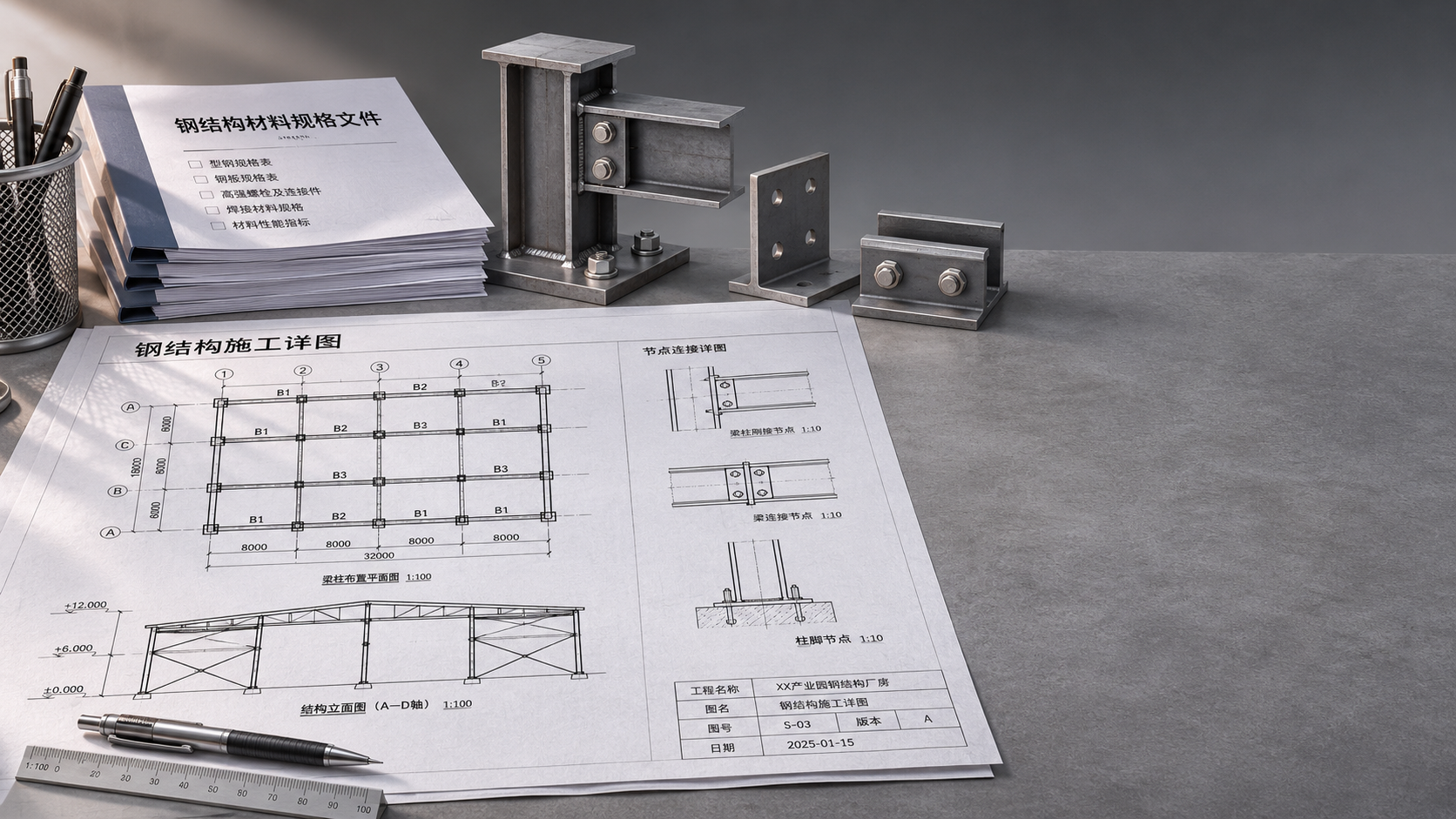
Steel structure design and fabrication require more than a set of building plans. A workable document package normally includes the project’s design criteria, architectural and structural information, material specifications, fabrication drawings, and inspection requirements. Depending on the scope, it may also include geotechnical reports, connection calculations, coating specifications, and erection documents.
The exact package depends on who is designing the structure, where it will be built, and how far the project has progressed. A manufacturer can often prepare a preliminary proposal from incomplete information, but fabrication should begin only after the responsible parties have resolved the design, drawing, material, and approval requirements that affect the steelwork.
Start by defining who is responsible for each document
Before collecting files, establish the division of design responsibility. The building owner, architect, structural engineer, steel fabricator, and erection contractor may each produce or review different documents. Their roles vary by contract and local requirements.
For example, an owner may appoint an engineer to design the primary structure while asking the fabricator to detail the members and design selected connections. In another project, the manufacturer may have a broader design scope. Those arrangements call for different deliverables and different approval steps.
A written scope should identify who provides the design loads, who designs connections and foundations, who prepares shop drawings, and who has authority to approve them. It should also state which documents must be submitted before fabrication and which records must accompany delivery. Without that agreement, a complete-looking drawing package can still leave a critical design responsibility unassigned.
Documents needed to establish the building design
The first group of documents tells the design team what the building must do and what constraints it must meet. For a warehouse or industrial facility, these inputs affect member sizes, bracing, connections, foundations, and interfaces with other trades.
Architectural drawings and building requirements
Architectural plans, elevations, and sections establish the building’s layout and intended dimensions. They should show the building footprint, grid lines, roof shape, elevations, openings, and intended internal clearances. Door locations, loading bays, partitions, and future expansion requirements can also affect the structural arrangement.
Industrial buildings may need additional information on cranes, equipment platforms, mezzanines, suspended services, or heavy wall-mounted equipment. A clear height shown on an architectural drawing, for instance, should be coordinated with roof framing, crane equipment, and services so that the usable clearance is understood by all parties.
At an early stage, conceptual drawings can be sufficient for a preliminary quotation. For final design, the information needs to be coordinated and developed far enough to define the loads and interfaces that influence the structure.
Design criteria and loading information
A design criteria document records the assumptions used by the structural engineer. It should identify the project location, applicable design codes and editions, intended building use, required design life where specified, and the loads or load criteria relevant to the project.
Depending on the building, these may include dead and imposed loads, wind, snow, seismic action, crane loads, equipment loads, and loads from suspended services. The document should also address project-specific performance requirements, such as deflection limits or movement allowances, where these are specified.
Geographic location alone is not a complete loading brief. Exposure, building geometry, intended occupancy, equipment operation, and local authority requirements can all matter. If crane data is incomplete, for example, the engineer may be unable to finalize the supporting beams, columns, bracing, and foundations even when the crane capacity is known.
Site and foundation information
A geotechnical investigation report provides the foundation designer with information about ground conditions and recommendations relevant to foundation design. A site survey may also be needed to establish levels, boundaries, and physical constraints.
The foundation scope should be explicit. Steel suppliers may provide column reactions and anchor bolt requirements without designing the foundations themselves. The foundation engineer needs the applicable reactions, load combinations, column base details, and any movement or construction constraints. In return, the steel detailing team needs coordinated foundation and anchor bolt drawings before finalizing base plates and erection details.
Structural design and approval documents
Structural design drawings translate the project requirements into a defined framing system. They identify the structural grid, member arrangement, sizes or designations, bracing, levels, and principal connection requirements. They may also include notes on materials, welding, bolts, tolerances, corrosion protection, and the standards governing the work.
Design calculations support the structural design and, where required, demonstrate compliance to reviewers or authorities. The required level of submission depends on the project, contract, and jurisdiction. Calculations may cover the overall frame, individual members, stability, foundations, and connections. Where connection design is delegated, the responsible connection designer’s calculations may be submitted separately.
Permit or statutory approval documents are another consideration. The design team should determine which drawings, calculations, forms, and professional endorsements the relevant authority requires before construction. A manufacturer’s production drawings do not automatically replace documents required for a building permit.
For cross-border projects, agree on the governing code, material grades, units, and documentation language early. A material designation or drawing convention familiar to the fabricator may need to be mapped to the project specification and accepted by the responsible engineer. Substitution should be documented and approved before purchasing or fabrication.
What the fabricator needs before production
Design drawings describe the intended structure; fabrication documents turn that design into instructions for making and assembling individual pieces. The handover between these stages is a common source of delay, especially when drawings have been issued while connection details, equipment loads, or architectural openings are still changing.
Shop drawings and connection details
Shop drawings show the information needed to fabricate each steel component. They normally include member marks, lengths, profiles, plate dimensions, hole locations, weld details, bolt requirements, and references to associated assemblies. Assembly drawings show how individual pieces fit together in the shop or on site.
Connection drawings deserve particular attention because they sit between structural design, fabrication, transport, and erection. A connection that satisfies the design also has to accommodate access for welding or bolting, available lifting space, and the sequence of assembly. If the fabricator is responsible for connection design, the contract should define the design forces, standards, submission requirements, and review process.
The drawing review procedure should state what approval permits. A reviewed shop drawing may authorize fabrication under the agreed procedure, but review does not necessarily transfer every design or dimensional responsibility to the reviewer. The contract and project approval process should make those responsibilities clear.
Material and workmanship specifications
Specifications set the requirements that may not fit on a drawing or that apply across many components. They should address the required steel grades and product standards, bolts and other fasteners, welding requirements, fabrication tolerances, inspection, surface preparation, and protective coatings where applicable.
Coating requirements are especially dependent on the building’s exposure and intended service conditions. A useful specification identifies the areas to be protected, required surface preparation, coating system, application requirements, and inspection or repair requirements. If some surfaces will be enclosed, site-welded, or difficult to reach after assembly, those conditions should be coordinated before the coating work is planned.
Where fire protection is required, the responsible design team should define the applicable performance requirement and the proposed protection system. The fabricator and other contractors then need to coordinate surface preparation, compatible coatings, connection details, and responsibility for applying and repairing the protection.
Revision-controlled production information
Fabricators need a clear record of which documents are approved for production. A drawing register can list each drawing number, revision, issue date, status, and any outstanding comments. The same control should extend to specifications, requests for information, approved substitutions, and design changes.
If a door opening moves after wall bracing has been detailed, simply sending a revised architectural plan may not be enough. The structural designer may need to reassess the bracing, the detailer must update affected drawings, and the fabricator needs to identify any material already ordered or work already completed. A documented change process makes those effects visible before the revised information reaches the shop.
Inspection, delivery, and erection records
Inspection requirements should be agreed before fabrication starts, not assembled after the steel has been made. The project specification or inspection and test plan can identify the checks to be performed, acceptance criteria, responsible parties, required records, and any inspection points that require notice or approval before work proceeds.
Depending on the project, the resulting package may include material certificates, traceability records, welding procedure and personnel qualification records, weld inspection reports, coating inspection records, and dimensional inspection reports. The contract should state which records are required and how individual materials or components are to be traced. The extent of testing and documentation should follow the project requirements rather than an assumed standard package.
For shipment and erection, packing lists, shipping lists, member mark lists, and erection drawings help the receiving team identify components and their intended locations. Erection drawings should coordinate with the approved structural and shop drawings and indicate the information needed to assemble the frame, including member marks, connection locations, and relevant bracing.
The erection contractor may also need an erection method statement, lifting plan, temporary bracing design, or other site-specific documents. Responsibility for preparing and approving these should be assigned in the contract. Permanent bracing shown on the final structural drawings may not by itself establish stability at every intermediate stage of erection.
How to check whether the package is ready
The most useful readiness check is to follow the information from design input to fabrication instruction. The architectural layout should agree with the structural grid and openings; design loads should include the equipment and services shown by other disciplines; foundation and anchor bolt details should match the column bases; and shop drawings should reflect the latest accepted design.
Before authorizing production, the project team should be able to answer four practical questions:
- Are the governing design criteria, loads, material requirements, and applicable standards documented?
- Are design responsibilities and required approvals clear, including responsibility for connections and foundations?
- Have the fabrication drawings and specifications been reviewed under the agreed procedure, with outstanding comments resolved?
- Are inspection requirements, required records, and the process for handling changes defined?
Some details may legitimately remain open during preliminary pricing or early design. They should be recorded as assumptions, with an owner and a date for resolution. Once material is ordered or fabrication begins, a change to one of those assumptions can affect several documents at once. The value of the package lies in keeping those documents coordinated as the project moves from a building concept to steel that can be fabricated, delivered, and safely erected.
We are more than happy to serve you here. If you have any question, please feel free to contact us.