
News center
Related Posts
- ▶ Prefab vs. Conventional Warehouse Construction: Comparing Timelines
- ▶ Planning a Prefab Warehouse: Clear Span, Height and Loading Bays
- ▶ How Long Does It Take to Build a Commercial Steel Building?
Online Message
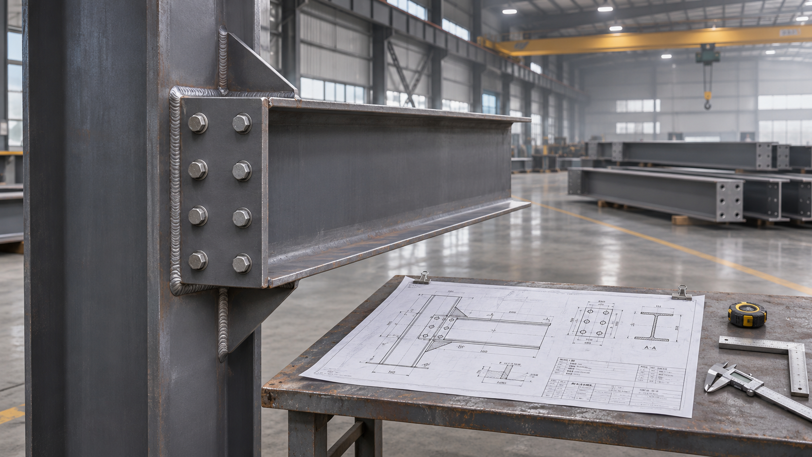
Coordinate steel structure design and fabrication by agreeing on design inputs, connection responsibilities, drawing release points, and installation constraints before production begins. The structural design establishes the required performance; fabrication drawings translate that intent into cut lengths, holes, welds, plates, and assemblies. Coordination succeeds when changes to either set of information are tracked and resolved before they affect material orders or workshop operations.
The most useful starting point is a shared project information package. It should identify the governing design criteria, applicable specifications, member geometry, connection requirements, surface treatment, delivery sequence, and site interfaces. Each item needs a responsible party and a status: confirmed, pending, or subject to revision. A drawing marked “approved” is of limited value if a critical load, opening, or foundation dimension remains unresolved.
Set the design and fabrication boundaries early
Before detailing starts, distinguish the structural design documents from the information the fabricator must develop. The design documents ordinarily define the structural arrangement, member sizes, design actions, stability system, and performance requirements. Shop drawings describe how individual pieces and assemblies will be made. They also identify marks, dimensions, welds, bolts, holes, and finishes.
Connections are a frequent source of uncertainty. A design drawing might show a beam meeting a column without fully defining the connection. The project must establish whether the connection is already designed or whether its design is delegated, what forces it must resist, and who reviews the resulting calculations and details. A connection selected only from the apparent member sizes can be inadequate if it must also transfer axial force, moment, or an erection load.
Record assumptions that affect the steelwork even when they originate outside the steel package. Examples include cladding support positions, equipment loads, crane clearances, fire protection thickness, and openings for services. A small change in an opening location can conflict with a stiffener or shift a splice into a less accessible position. Identifying the owner of each input makes it easier to resolve such conflicts without circulating drawings indefinitely.
Turn the structural model into buildable details
A coordinated model is useful only when its dimensions and details match the intended fabrication method. Establish a common grid, elevation reference, and unit system, then reconcile the model with architectural, foundation, and equipment information. Model exchanges should identify the revision and scope of the data; a transferred file is not automatically an approved fabrication release.
Pay particular attention to interfaces where dimensions come from different sources:
- Base plates and foundations: Align column grid positions, base plate elevations, anchor rod patterns, projection lengths, and grout allowance. Confirm whether dimensions refer to the finished concrete surface, the top of grout, or the underside of the plate.
- Beam-to-column connections: Coordinate plate thickness, bolt access, weld access, and the space needed to place and tighten bolts. A connection that fits in the model can still be difficult to assemble if a tool cannot reach it.
- Bracing and secondary steel: Confirm gusset plates, purlin supports, sag rods, and bracing clearances alongside doors, ducts, and cladding rails.
- Splices: Locate them with structural demands, transport limits, lifting capacity, and site access in view. Moving a splice changes more than the shipping length: it can alter forces, bolt quantities, and erection stability.
Detailing should also allow for fabrication sequence. A plate welded inside a closed or obstructed assembly may be difficult to reach after adjacent parts are attached. Similarly, a hole pattern that clears the connected plate on screen may leave too little room for a bolt head, washer, or tightening tool. Reviewing these details as assemblies, rather than as isolated members, exposes problems while they are still inexpensive to correct.
Make tolerances part of the interface
Steel fabrication, concrete construction, and site erection each introduce dimensional variation. The connection detail must accommodate the combined effect where the trades meet. For example, anchor rod position, base plate hole size, column setting, and grout space have to work together; considering the tolerance of each component separately does not establish whether the assembly will fit.
Oversized or slotted holes are not a universal remedy. Their use affects the connection detail, washer requirements, and potentially its structural behavior. Any adjustment feature should be shown on the approved drawings and assessed against the design intent. Where movement cannot be accommodated by the detail, the dimensions must be verified before the affected steel is released.
Agree on material and workshop constraints before release
Material grade and section size influence both structural performance and fabrication. Confirm the specified grades for main members, plates, bolts, and welding consumables, along with any required material identification and documentation. Two sections with similar dimensions are not necessarily interchangeable: differences in strength, thickness, availability, or local section properties can affect the design and the connection.
Substitutions need a defined approval route. A proposed alternative should state the original and replacement material, affected members, dimensional differences, and consequences for connections and fabrication. Changing a plate thickness, for example, can alter bolt grip length, edge distances, and alignment with adjoining pieces. Approval of the material alone does not automatically approve every detail affected by it.
Discuss the workshop process while the details are still flexible. Plate cutting, drilling, punching, welding, straightening, and coating all impose practical constraints. A detail requiring a tight weld location or complex access may need a revised assembly sequence. Where a welded section is substituted for a rolled section, review the resulting geometry, weld requirements, and connection fit rather than assuming that the nominal depth is sufficient for equivalence.
Surface preparation and coating decisions belong in this discussion. Contact surfaces, field weld locations, bolt slip surfaces where applicable, and areas enclosed after assembly can require different treatment from exposed steel. The drawings and coating specification should identify these areas clearly. Leaving all coating decisions until after fabrication can make inaccessible surfaces difficult to prepare or protect.
Control drawing releases and design changes
Separate a drawing issued for coordination from one released for fabrication. A practical release identifies the drawing revision, the components covered, outstanding comments, and any restrictions on work. Review comments should be closed or explicitly carried forward with an owner and a due date. If approval is conditional, the condition must be visible to the people preparing cutting files and shop work orders.
Link each production package to the approved drawings, model revision, material lists, and machine data used to produce it. A revised drawing does not by itself update a previously exported cutting file or a printed copy at a workstation. When a change is issued, identify the affected piece marks and trace them through material ordering, cutting, assembly, welding, coating, and dispatch.
The response depends on how far the work has progressed. If material has not been cut, a revised cutting plan may resolve the change. Once a connection plate is welded, the change may require removal and repair, engineering review, or replacement of the assembly. Changes to fabricated steel should be documented with the proposed repair and acceptance process; an informal site instruction can leave the final configuration inconsistent with the design records.
Requests for information work best when they include the exact location, conflicting documents, proposed interpretation, and the date by which an answer is needed to avoid holding a specific activity. For example, “confirm the bracing connection” is difficult to answer quickly. Identifying the grid, elevation, member marks, and clash between the gusset plate and a service opening gives the response a defined scope.
Coordinate quality checks with fabrication stages
Inspection is most effective when it is tied to work that will later become inaccessible. Material identification can be verified before pieces are mixed or cut. Fit-up can be checked before welding conceals the joint. Hole positions and overall geometry can be measured before coating or shipment. The inspection plan should identify the required records, acceptance criteria, and any hold points established by the project specification.
Weld requirements need to be clear on the drawings and supported by the applicable project procedures. Specify the weld type, size, extent, and inspection requirements where required. A symbol that is unclear about which side of a joint is welded can result in a completed assembly that looks plausible but does not match the design. Where inspection or testing is specified, access for it must also be considered in the assembly sequence.
Dimensional checks should focus on functional relationships as well as individual measurements. A beam length can be correct while the end plate is rotated, and a hole group can be accurately drilled but positioned from the wrong datum. Measuring between connection points, checking squareness, and confirming the orientation of marked faces helps establish whether parts will fit together on site.
For repeated assemblies or complicated interfaces, a trial assembly can reveal a mismatch before multiple pieces are completed. It is most useful when the trial reproduces the relevant connection geometry and uses the intended bolt and plate arrangement. Its scope and acceptance criteria should be agreed in advance; a trial of one joint does not verify every dimension of the structure.
Plan fabrication around transport and erection
The fabrication sequence should reflect the planned erection sequence. If the first delivery contains roof members but the columns and bracing needed to stabilize them are unavailable, early production does not translate into useful site progress. Group piece marks into erection areas or sequences, and keep the packing list aligned with those groups.
Shipping limits affect member length, assembly size, and the location of field splices. Lifting equipment and site access impose further constraints: a long member that fits on a vehicle may still be difficult to unload or rotate into position. Confirm these limits before finalizing splice locations and lifting details, and account for temporary conditions during erection as well as the completed structure.
Field connections also need space for assembly. A connection designed for shop welding may need to be revised if access, weather protection, or inspection at the site makes that weld impractical. Conversely, changing to a bolted detail affects plates, holes, bolt access, and potentially the structural design. The revised detail should pass through the same engineering and drawing controls as the original.
Before dispatch, piece marks, quantities, loose connection materials, and delivery documents should correspond to the released erection drawings. Where site measurements reveal a foundation or anchor rod discrepancy, record the actual dimensions and assess the affected interfaces before modifying the steel. That preserves a clear path from the observed condition to an approved detail and an updated as-built record.
We are more than happy to serve you here. If you have any question, please feel free to contact us.