
Related Posts
- ▶ Prefab vs. Conventional Warehouse Construction: Comparing Timelines
- ▶ Planning a Prefab Warehouse: Clear Span, Height and Loading Bays
- ▶ How Long Does It Take to Build a Commercial Steel Building?
Online Message
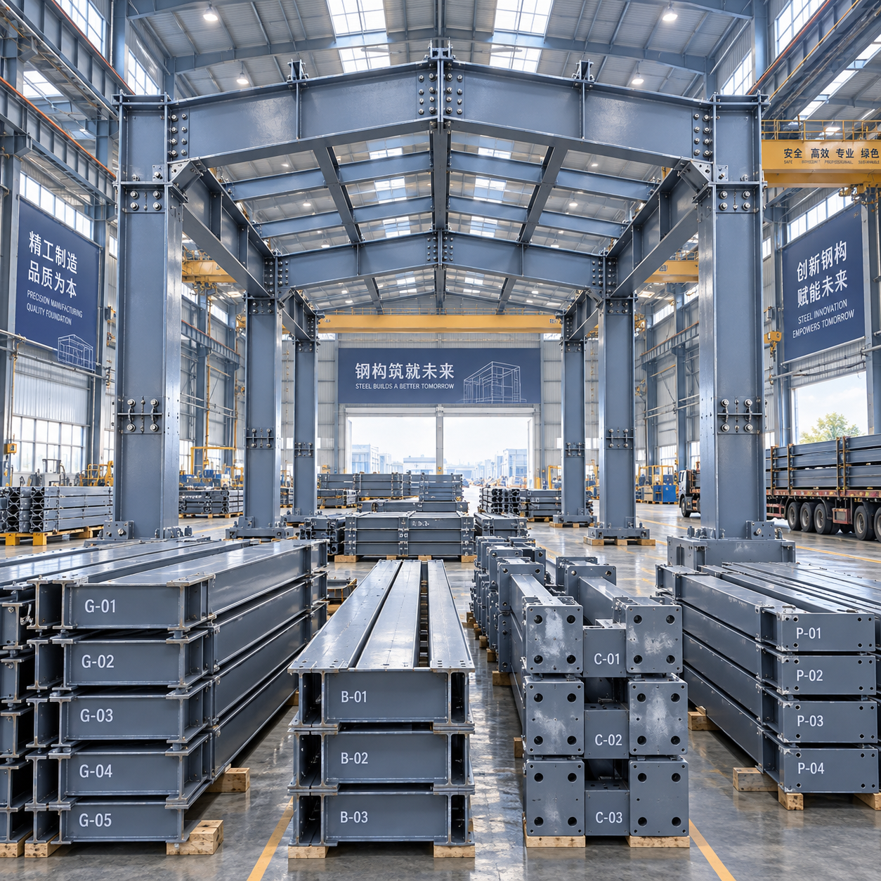
A steel building is not made reliable by fabrication quality alone, nor by a structurally sound calculation completed in isolation. Its performance depends on whether design assumptions, connection details, material specifications, shop drawings, factory controls, logistics, and erection methods remain aligned from the first brief through final handover.
The steel structure design and fabrication workflow is therefore best understood as a controlled chain of decisions rather than a simple sequence of engineering and manufacturing tasks. Errors introduced early—an unclear loading basis, an omitted service opening, a connection that cannot be bolted on site, or a coating system unsuitable for the local exposure category—can become expensive only after steel has been cut, drilled, painted, shipped, or erected.
1. Establishing the design basis before structural work begins
The first stage is defining what the building must do, under which conditions, and to which governing requirements. This is more than collecting plan dimensions. The design basis should convert commercial and architectural requirements into technical inputs that can be checked and traced through later stages.
For an industrial warehouse, workshop, logistics building, or agricultural facility, the essential inputs commonly include:
- Building dimensions, eave height, roof geometry, grid spacing, and expansion requirements;
- Intended occupancy and process loads, including suspended equipment, crane loads, racking interfaces, photovoltaic systems, and future mezzanines;
- Site-specific environmental loads such as wind, snow, rainwater ponding, seismic action, temperature range, and corrosion exposure;
- Local building regulations, fire-resistance requirements, and the structural design standard required by the authority or contract;
- Foundation concept, soil information, and responsibility boundaries between the steel supplier, civil designer, and erection contractor;
- Architectural constraints involving roof and wall systems, daylighting, doors, ventilation openings, drainage, and service penetrations.
This stage is where many avoidable scope disputes originate. A building may be described as a “standard portal-frame warehouse,” yet the addition of a crane runway, substantial rooftop equipment, a high wind zone, or a large number of wall openings can materially alter member sizes, bracing arrangements, connection forces, and cost.
Standards must also be identified early. Structural steel may be designed under systems such as AISC-based requirements, Eurocodes, AS/NZS standards, or project-specific national codes. Material standards and fabrication standards are related but not interchangeable. Specifying ASTM steel grades does not, by itself, define the applicable structural design method, welding acceptance criteria, bolt installation requirements, or inspection regime.
2. Selecting the structural system and load path
Once the design basis is stable enough for engineering, the designer determines how loads will travel through the building to the foundations. The most economical frame is not necessarily the lightest frame on a weight basis. It is the system that satisfies structural, architectural, fabrication, transport, and installation constraints with the fewest costly complications.
Typical options include portal frames, multi-span rigid frames, braced steel frames, trusses, built-up plate girders, lattice columns, mezzanine systems, and composite arrangements. The appropriate choice depends on span, height, loading pattern, internal clearance requirements, transport limits, and the degree of future flexibility needed.
A portal frame can be efficient for clear-span low-rise buildings, but its knee and apex details require careful treatment. A truss may reduce steel weight over a long span, yet introduce more members, gusset plates, welding, inspection points, and erection interfaces. A braced frame may be materially efficient, but its bracing may conflict with loading doors, glazing, conveyors, or internal circulation. These are not merely architectural preferences; they influence the entire fabrication and installation plan.
The load path should be explicit for gravity loads, lateral wind and seismic loads, crane actions where applicable, and accidental or stability-related effects. Roof sheeting may contribute diaphragm action only when it has been designed and detailed to do so. It should not be assumed to compensate for missing bracing without a verified structural design basis.
3. Structural analysis and member design
The analysis stage tests whether the proposed system can resist the required actions without exceeding strength, stability, serviceability, or connection limits. Modern engineering software makes analysis faster, but it does not remove the need for sound modeling assumptions. The model must represent the actual structural behavior intended for fabrication and erection.
Key engineering checks generally include member strength, lateral torsional buckling, column buckling, frame sway, deflection, vibration where relevant, connection capacity, base plate behavior, and foundation reactions. Serviceability is often as important as ultimate strength. A roof frame may satisfy strength requirements while still producing excessive deflection that affects drainage, cladding performance, door operation, suspended services, or visual appearance.
Connection design deserves particular attention because connections define how idealized analysis models become real structures. A rigid moment connection, a nominally pinned connection, and a braced connection impose different demands on plates, bolts, welds, member end geometry, and erection sequence. A connection that works in calculation may still be difficult to access with tools, impossible to weld in the intended position, or impractical to inspect after coating.
Design coordination should also address secondary steel: purlins, girts, eave struts, sag rods, bracing members, roof curbs, platform supports, stairs, handrails, and cladding support framing. These components are sometimes treated as minor details, but they frequently drive local loads and site adjustments. The support locations for mechanical units, cable trays, sprinkler mains, roof access systems, and façade attachments should be resolved before fabrication release wherever possible.
4. Converting engineering into coordinated shop drawings
Design drawings establish structural intent. Shop drawings translate that intent into individual parts and assemblies that can be fabricated, inspected, shipped, and erected. This is one of the most consequential stages in the steel structure design and fabrication workflow because it connects engineering calculations with physical production.
Detailed drawings normally identify member marks, plate thicknesses, steel grades, cut lengths, hole sizes, bolt types, weld symbols, connection geometry, camber requirements, assembly marks, and surface treatment requirements. They also show how components are divided for transport and how site joints will be completed.
At this point, design for manufacture and assembly becomes critical. A fabricated member may need to be split because of road transport limits, container dimensions, lifting capacity, or coating-bath constraints. That split creates a field splice, which then needs accessible bolts, tolerances for erection, and a clear installation sequence. A detail that saves a small amount of steel in the factory can create disproportionate site labor if it requires difficult welding at height or relies on tight alignment tolerances.
Coordination with the civil works is equally important. Anchor-bolt setting plans, base plate dimensions, column reactions, pedestal elevations, and allowable construction tolerances need to be issued in time for foundation construction. Steel erection can be delayed by only a few millimeters of anchor-bolt deviation when base plate holes and leveling allowances have not been designed realistically.
Drawing approval should not be confused with passive document circulation. It is the point at which unresolved questions must be closed: Which party provides crane brackets? Are cold-formed purlins designed for the exact roof panel system? Is the fire-protection approach compatible with the specified coating? Do insulated wall panels alter girt spacing or fastener requirements? Late answers become revisions, rework, or site variation orders.
5. Material procurement and traceability control
Steel procurement begins after specifications and detailing have defined what is actually required. The purchasing task is not simply to obtain steel sections and plates of the right nominal size. It must ensure that material grade, thickness, mechanical properties, certification, and identification are consistent with the approved documents.
Mill test certificates are commonly used to document chemical composition and mechanical properties for structural steel. Their role is useful only when traceability is maintained. Material receiving procedures should connect the certificate, heat number or batch identifier where applicable, stock record, and fabricated part. Once plates are cut into smaller components, identification methods must preserve the ability to verify critical material where the contract or quality plan requires it.
Substitution risk deserves careful control. A steel grade with similar yield strength may differ in toughness, weldability, thickness availability, or governing standard. Similarly, bolts, welding consumables, and protective coatings must be compatible with the specification and intended environment. A coating system should be selected by considering surface preparation, corrosion category, expected service conditions, repair requirements, and compatibility with fire-protection systems if used.
Procurement timing affects more than the factory schedule. Delays in specialty plate thicknesses, high-strength bolts, approved coating materials, or proprietary cladding interfaces can interrupt fabrication after work has already started. A credible production plan identifies long-lead items before cutting begins.
6. Cutting, drilling, fitting, and welding in the factory
Fabrication transforms approved drawings into parts and assemblies. Typical operations include plate cutting, section cutting, edge preparation, drilling or punching, bending where required, fit-up, welding, grinding, straightening, trial assembly, and marking. The objective is not merely dimensional completion; every operation needs to preserve the tolerances and structural properties assumed in design.
Computer-controlled cutting and drilling can improve repeatability, but machine accuracy does not eliminate process control. Material can distort under thermal cutting and welding. Long built-up members may require welding sequences that limit residual distortion. Holes must align with field connections after transport and coating. Weld access must be considered during fit-up rather than discovered after plates are assembled.
Welding requires qualified procedures appropriate to the joint type, material, thickness, position, and applicable code. The quality plan may require visual inspection, dimensional checks, and, for designated critical welds, non-destructive examination such as ultrasonic, magnetic particle, or dye penetrant testing. The required method and extent should be defined by the contract documents and relevant fabrication standard, rather than applied indiscriminately to every weld.
Bolted connections also demand discipline. Hole type, bolt grade, washer arrangement, tightening method, and slip-critical requirements must match the connection design. Site bolts should not be treated as interchangeable consumables. Incorrect bolt substitution can affect strength, ductility, corrosion resistance, or installation performance.
7. Factory inspection, surface treatment, and release for shipment
Inspection occurs throughout fabrication, not only at final release. Incoming material verification, fit-up inspection before welding, weld inspection, dimensional measurement, and assembly checks prevent defects from moving downstream. The later an error is found, the more expensive correction becomes.
Final dimensional inspection should focus on features that affect erection: overall member length, connection centerlines, splice locations, base plate geometry, column plumbness allowances, bracket positions, and bolt-hole alignment. For complex assemblies, trial fitting can identify interface problems before shipment, although it does not replace disciplined detailing and dimensional control.
Surface preparation and coating are functional stages, not cosmetic finishing. Blast cleaning, power-tool cleaning, galvanizing, or paint application must follow the specified system and required preparation level. Coating thickness, curing conditions, edge treatment, and damage repair procedures matter because corrosion often begins at poorly prepared edges, weld areas, fastener interfaces, and handling damage.
Before packing, each component should be marked to correspond with erection drawings and packing lists. Bundling must protect secondary members from bending while remaining practical for unloading. Small but critical items—connection plates, bolts, shims, closure pieces, and special brackets—need separate identification. Missing accessory parts can stop an erection crew even when the main frame has arrived.
8. Transport planning and site readiness
Fabrication is not complete in commercial terms when steel leaves the factory. Shipment planning must account for piece dimensions, weight, packaging, lifting points, route restrictions, customs documentation where cross-border delivery is involved, and the order in which bundles will be needed on site.
A sound delivery sequence mirrors erection logic. Columns, primary beams, temporary bracing components, connection hardware, and secondary framing should not arrive in a random order that creates unloading congestion or forces repeated handling. Long storage periods at site can also damage coatings, mix member marks, or expose bolts and accessories to loss.
Site readiness should be verified before delivery. Foundations need accepted survey records; anchor bolts need checking against the issued setting plan; access roads and crane standing areas must support the planned equipment; and adequate laydown space is needed to separate members by erection zone. Steel erection frequently appears to be a field problem when the cause is actually incomplete interface planning between civil and steel packages.
9. Erection, alignment, and completion of structural connections
Installation begins with setting columns and establishing a stable initial frame. Temporary bracing, erection sequencing, crane capacity, wind limits, and lifting arrangements should follow an engineered erection method rather than improvised site practice. A frame may be structurally complete only after all permanent bracing, purlins, girts, and connection bolts are installed; partially erected steel can be vulnerable to wind and construction loads.
Alignment checks are normally made as the frame progresses, not left until the end. Column position, plumbness, frame spacing, ridge elevation, and diagonal geometry affect whether roof and wall systems can be installed without forced adjustments. Shims, grout, base-plate leveling, and bolt tightening need to follow the approved details and applicable installation requirements.
Field welding, if specified, requires particular control because weather, access, welding position, and site power conditions differ from factory conditions. Where possible, bolted field splices reduce site welding exposure, but this only works when fabrication tolerances, bolt-hole arrangements, and lifting sequence have been designed accordingly.
10. Handover is a verification stage, not an administrative formality
A completed steel structure should be supported by a coherent record set: approved drawings, material certificates where required, welding documentation, inspection records, coating reports, bolt installation records where applicable, non-conformance resolutions, and as-built information. The exact documentation level depends on the contract, code, and project risk, but the principle is consistent: the completed building should be demonstrably aligned with the approved design and quality requirements.
The most reliable projects manage the interfaces between stages instead of treating each stage as a separate supplier responsibility. Engineering must understand fabrication constraints; detailing must account for transport and erection; procurement must preserve specification compliance; factory quality control must support field fit-up; and installation planning must reflect the structure actually delivered.
That integration is what distinguishes a steel package that is merely manufactured from one that can be erected safely, predictably, and with the durability expected over its service life.
We are more than happy to serve you here. If you have any question, please feel free to contact us.