
Related Posts
- ▶ Prefab vs. Conventional Warehouse Construction: Comparing Timelines
- ▶ Planning a Prefab Warehouse: Clear Span, Height and Loading Bays
- ▶ How Long Does It Take to Build a Commercial Steel Building?
Online Message
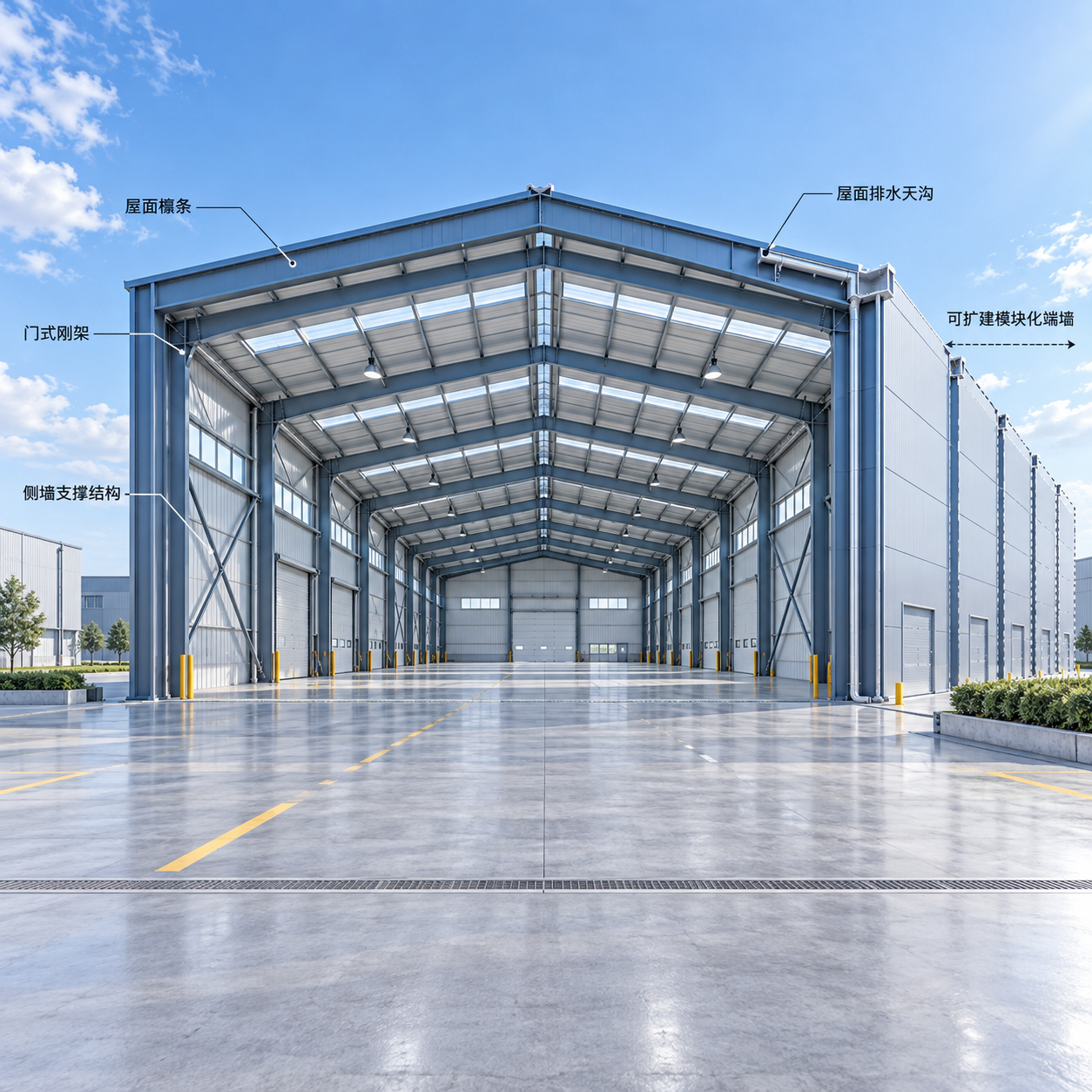
A steel building can look straightforward on an early layout: a rectangle, a roof, a few door openings, and enough floor area for storage or production. The difficult decisions usually appear when the initial sketch is tested against real use. A warehouse may need racking near the walls, a workshop may require an overhead crane, or an agricultural building may need to remain open for machinery. Each condition changes the structural demands long before steel is fabricated.
The central rule of Steel Building Design is to define loads, usable span, and likely expansion at the same time. These are not separate selections made by different parties. A larger clear span can change frame depth and foundation reactions; a future extension can affect end-wall detailing and drainage; an overlooked equipment load can require a different primary frame. Early planning does not need every final detail, but it does need a realistic operating brief that the structural design can test.
Start with the building’s working conditions, not only its floor area
Two buildings with the same length and width may require very different structural systems. The plan dimensions describe the footprint, but they do not explain what happens inside, what acts on the roof, or how the building may change over time. Before comparing frame options, define how the space will work on a normal day and under less frequent but demanding conditions.
For example, a storage facility may require a wide unobstructed loading aisle, tall pallet racks, dock doors, and vehicle movement near columns. A fabrication workshop may need large equipment positioned in fixed zones, a crane runway, roof-mounted services, and frequent opening cycles at one end. A farm structure might have relatively light internal use but large door openings, exposure to wind, and changing moisture conditions. These are operational inputs, yet they become structural inputs quickly.
A useful early brief records the following:
- building length, width, eave height, roof form, and intended internal clear height;
- primary activities, including storage, manufacturing, maintenance, livestock, vehicle access, or public circulation;
- equipment that bears on the structure, such as cranes, suspended utilities, solar arrays, ventilation units, pipe racks, or ceiling systems;
- locations and dimensions of doors, windows, louvers, mezzanines, and large wall penetrations;
- site conditions, including wind exposure, snow potential, seismic requirements where applicable, soil information, drainage, and corrosion exposure;
- future changes that are probable rather than merely possible.
This information helps prevent a frequent early-stage mistake: selecting a building form based only on a preferred width or a familiar bay spacing, then discovering that the required openings, loading, or internal circulation cannot be accommodated efficiently.
Loads determine more than steel member size
Loads are often discussed as a calculation issue, but their practical effect is much broader. They influence frame spacing, column locations, bracing layout, connections, foundations, cladding support, and the ability to add equipment later. The load path must be clear: roof and wall loads transfer through secondary members and primary frames into columns, foundations, and soil. Interruptions in that path, including large openings or unusual attachments, need deliberate treatment.
Permanent and imposed loads
Dead load is the permanent weight of the structure and its fixed components. It can include framing, roof and wall cladding, insulation assemblies, fixed ceilings, permanent service runs, and installed rooftop equipment. Early budgets sometimes assume a basic roof load while later adding photovoltaic panels, heavy ductwork, or equipment platforms. That sequence can create redesign work because the roof system and frame may need to carry substantially more than the original allowance.
Live load refers to variable loading associated with use, maintenance, or occupancy. Roof live loads can be affected by access and maintenance requirements. Floor live loads depend on the intended use of slabs, mezzanines, storage areas, and platforms. Where racking, machinery, or concentrated storage is expected, the relevant issue is not just total weight. Point loads, wheel loads, leg loads, and repetitive traffic can govern local slab and foundation design.
Environmental actions shape the frame
Wind, snow, rain accumulation, seismic action, and temperature movement must be considered according to the applicable local requirements and site conditions. Their effects are rarely limited to a single member. Wind may govern wall bracing, uplift connections, roof edge details, and foundation hold-down forces. Snow can create uneven roof loading where drifting occurs near height changes, parapets, adjacent structures, or projections. Rainwater ponding needs attention on low-slope roofs because deflection can alter drainage behavior and increase localized loading.
Wind exposure deserves early discussion when a building is located on open ground, near water, on elevated terrain, or beside taller structures. A broad wall with large doors behaves differently from a largely enclosed wall. Open-sided or partially enclosed buildings can experience internal pressure effects that should not be treated as a minor variation of a fully enclosed warehouse.
Special loads are where early assumptions fail
Cranes, suspended loads, mezzanines, rooftop units, conveyors, and equipment platforms should be identified before primary frame selection. A crane-supported building is not simply a standard building with rails added later. Crane capacity, runway elevation, wheel loads, impact effects, lateral forces, duty cycle, and clearance requirements all affect columns, bracing, and foundations.
Similarly, a mezzanine changes more than usable floor area. It introduces vertical loads, lateral stability considerations, stair and guard requirements, fire or access implications where applicable, and possible conflicts with vehicle routes or equipment below. When a future mezzanine is likely, reserving load capacity and connection locations may be more practical than retrofitting a completed envelope.
Clear span is a functional decision before it is an engineering decision
A clear span is the distance between primary supports without interior columns. It is valuable where uninterrupted movement, flexible layouts, or large equipment access matter. Warehouses often benefit from clear spans that allow storage arrangements to change. Workshops may need open space for fabrication lines, lifting operations, or vehicle turning. Agricultural and aircraft-related facilities may require broad openings and internal clearance that columns would obstruct.
However, “maximum clear span” is not automatically the best brief. As span increases, primary frame members may become deeper or heavier, and lateral stability, deflection, erection logistics, and foundation forces may also change. A building with fewer columns can improve operations while increasing structural cost or reducing options for placing services. The appropriate choice depends on the value of the open floor area compared with those structural effects.
Clear span also needs to be considered vertically. A building can have no interior columns but still be unsuitable if roof framing, crane girders, lighting, ductwork, or sprinkler lines reduce the usable height. Specify the required clearance at the locations where it matters: beneath the haunch, below crane components, at door heads, over travel lanes, and above stored goods.
Frame spacing and bracing affect the usable building envelope
Frame spacing is the distance between repeated primary frames along the building length. It influences secondary member spans, cladding support, roof layout, structural weight distribution, and the placement of doors and internal partitions. A regular spacing can simplify coordination, but a single large opening or an equipment zone may justify a local adjustment.
Bracing is another item that should appear on early plans. It provides stability against longitudinal and lateral forces, but it occupies real wall or roof zones. A diagonal braced bay placed where a future loading door is needed can create a costly conflict. The same issue arises when bracing is planned behind a full-height window band, a conveyor route, or a circulation opening.
Ask for bracing zones to be shown on concept drawings rather than assuming they can be placed anywhere later. Where conventional cross bracing conflicts with access, the structural system may need another approach, such as rigid framing or carefully designed alternative bracing arrangements. The correct option depends on loading, geometry, code requirements, and the overall building system; it should not be selected merely to keep one wall visually clear.
Plan expansion while the end wall is still only a line on a drawing
Expansion is easiest when its direction, constraints, and trigger points are considered before construction. The most common extension is lengthwise, where a removable or adaptable end wall allows additional bays to be added. Width expansion is often more complicated because it can interfere with roof slopes, drainage, structural framing, and adjacent site space. Vertical expansion can be even more restrictive if columns, foundations, and lateral systems were not designed for it.
A future extension does not always mean the initial building must be fully engineered for the final size. It does mean the first phase should avoid blocking the likely route of growth. Site utilities, stormwater paths, vehicle circulation, fire access, retaining works, and neighboring structures can make a theoretically expandable wall unusable in practice.
During early planning, distinguish among three levels of expansion intent:
- Possible expansion: The owner would welcome more space someday but has no defined use or timeframe. Preserve site access and avoid irreversible obstacles, but do not assume heavy future loads without evidence.
- Planned expansion: A likely extension direction and approximate footprint are known. Coordinate end-wall configuration, roof drainage, foundations near the joint, and utilities so the next phase can connect cleanly.
- Staged construction: The complete building is already conceptually defined but will be built in phases. Structural interfaces, temporary weather protection, bracing during each phase, and final load paths require coordinated design from the outset.
Drainage is easily overlooked in expansion planning. A future addition can redirect roof runoff, create valleys, or place new gutters against existing walls. A simple initial roof may become a drainage problem after the second phase unless slopes, downpipes, and site drainage are planned as a connected system.
Openings and attachments need structural coordination
Door openings are not merely cladding decisions. Their width, height, operating type, and position can remove wall areas that would otherwise carry bracing or support girts. Large vehicle doors may require reinforced jambs, head members, and special attention to wind pressures when open or closed. Multiple openings close together can leave narrow wall segments with limited capacity for structural functions.
Canopies, awnings, equipment platforms, signs, suspended pipework, and façade features also impose loads and connection demands. They should be identified before shop detailing. Adding them after the primary design is complete may require local strengthening and can complicate weatherproofing around penetrations.
The same principle applies to structures outside the main envelope. In infrastructure or architectural settings, steel systems used to span a route or connect spaces must be evaluated around support conditions, live loading, movement, and interface geometry. Where a project includes pedestrian or vehicle crossing requirements alongside a building, Landscape Bridge Systems can be considered as a separate steel application, provided its support design and load criteria are coordinated with the surrounding works rather than assumed to follow the building frame.
Use a staged decision process before requesting a final proposal
Early design becomes more reliable when decisions are made in the order that reduces rework. First establish the activity inside the building and the site constraints. Next identify loads and clearance requirements. Then test span, bay spacing, bracing, openings, and expansion direction together. Only after these relationships are clear should the design move toward detailed member sizing, connections, cladding selection, and fabrication drawings.
At the concept stage, it is reasonable to compare alternatives: a wider clear span versus interior columns, a higher eave versus a different storage arrangement, or a prepared expansion end versus a later standalone addition. The comparison should include operational consequences, not just initial steel quantity. A less expensive frame can become restrictive if it places columns in travel routes or prevents a planned crane installation. Conversely, a very large span may provide unused flexibility while increasing structural demands without a clear business purpose.
Local building code requirements, site-specific environmental actions, geotechnical information, and final equipment data should be confirmed before construction documents are issued. Those inputs are especially important when the building includes cranes, large openings, unusual roof loads, high wind exposure, seismic design requirements, or phased expansion. A well-defined brief at this point allows the structural system to be developed around real conditions rather than revised repeatedly after fabrication decisions have begun.
We are more than happy to serve you here. If you have any question, please feel free to contact us.