
Related Posts
- ▶ Prefab vs. Conventional Warehouse Construction: Comparing Timelines
- ▶ Planning a Prefab Warehouse: Clear Span, Height and Loading Bays
- ▶ How Long Does It Take to Build a Commercial Steel Building?
Online Message
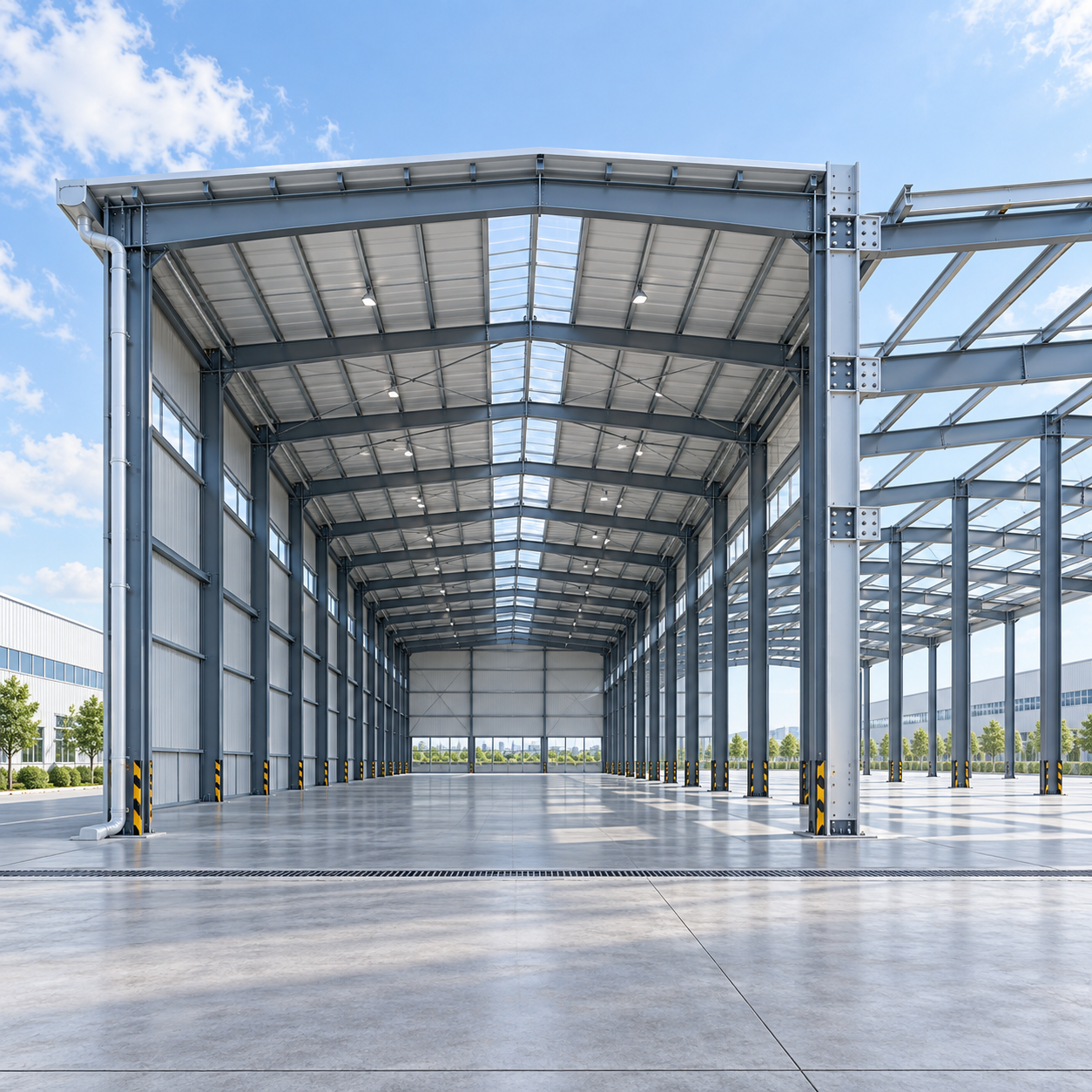
Future expansion becomes expensive when the original structure has no predictable place to grow. The cost is rarely limited to extra steel. It can include removing cladding, relocating loading areas, interrupting production, strengthening foundations, rerouting drainage, modifying fire separation, and dismantling electrical or mechanical work that was recently installed. A disciplined Steel Building Design reduces these avoidable costs by treating expansion as a physical condition to be planned, not a vague possibility reserved for a later phase.
The most economical starting point is to define the likely direction of growth before finalizing the first building footprint. A warehouse may need additional storage bays at one gable end; a production building may require a side extension for a new process line; a logistics facility may need more dock positions rather than more floor area. These are different expansion problems. A building designed for end-wall extension can still be costly to widen, while a structure prepared for side bays may not accept new loading doors without reworking internal traffic routes.
Set the structural grid around repeatable growth
A regular bay spacing is one of the most practical decisions in expandable steel construction. When column lines, purlin spacing, roof slopes, bracing locations, and cladding panels follow a repeatable module, a future addition can use the same geometry instead of becoming a custom transition project. Repetition also simplifies drawings, fabrication details, erection sequencing, and replacement part identification.
The module must match operations rather than simply use a convenient steel span. Storage racking, forklift aisles, pallet dimensions, production equipment, vehicle turning paths, and dock spacing often establish more useful planning dimensions than the frame alone. If racking rows are slightly misaligned with the column grid, the initial layout may still function, but every later bay addition can compound the lost storage area or force costly rack reconfiguration.
Grid discipline matters at the roof line as well. A future extension is easier to weatherproof when the existing eave, roof pitch, gutter arrangement, and wall-panel module anticipate a repeated bay. An irregular last bay, a changed roof slope, or a drainage path that terminates at the intended connection point can turn a simple expansion into a redesign of the roof edge.
Do not confuse a regular grid with unlimited flexibility
Longer bays can reduce the number of columns, but they may require heavier primary members, deeper purlins, or more demanding connections. Shorter bays may suit future subdivisions and support more roof-mounted services, yet they can create more column interference at grade. The right grid is the one that preserves a credible future layout without imposing unnecessary steel weight or operational obstruction on the first phase.
It is useful to reserve at least one expansion interface that is structurally legible: a designated end wall or side line where future members can connect, drainage can continue, and access can remain open during construction. This is more reliable than assuming that any wall can be removed later. Every wall can be altered in theory; the question is how much of the adjacent structure, services, and finished site must be disturbed to do it.
Choose clear-span space where change is likely to occur
Clear-span framing is often justified by adaptability rather than by floor area alone. In a warehouse, internal columns can constrain racking changes, conveyor installations, high-bay equipment, staging areas, and vehicle circulation. In a factory, columns placed inside a future production zone may restrict machine replacement even when they do not interfere with the first equipment layout.
Clear spans are not automatically the lowest-cost choice. Their economics depend on building width, roof loading, crane requirements, local wind and seismic actions, and the usable height needed below the rafters. A wide clear span may increase primary steel size, transport weight, and erection lifting requirements. Yet avoiding a permanent line of interior columns can be less expensive than moving them later, especially where floors contain machinery foundations, embedded utilities, or contamination-controlled finishes.
A hybrid arrangement can be more rational than applying clear span everywhere. For example, a clear-span production or storage zone can sit beside a multi-bay office, maintenance, or utility strip where columns are less disruptive. Separating these functions preserves adaptable high-value space while controlling the structural premium across the full footprint.
Column placement should also be reviewed against doors, truck routes, and possible external canopies. A column that appears harmless on a plan may block a future loading opening, force an awkward dock door spacing, or conflict with a vehicle sweep path. The operational drawing and structural drawing need to be reviewed together before fabrication release.
Design the frame for a planned connection, not just a removable wall
An expandable end wall needs more than removable cladding. The current frame must remain stable after the wall bracing is removed, and the future frame must have a defined load path. Bracing is commonly located in end-wall bays because it is efficient and visually unobtrusive. Removing that bracing later without a replacement system can alter the building's lateral behavior and trigger substantial strengthening work.
Early design should identify where longitudinal bracing will sit after extension. Options can include a braced bay retained within the original building, a new braced bay in the addition, or a moment-resisting arrangement where suitable. The selection must account for door openings, internal circulation, wall panels, and the sequence of temporary stability during construction. Leaving the issue until the addition is ordered often produces an extension that is technically possible but operationally compromised.
Connection details deserve similar attention. Future columns may require base plates and foundations sized for later reactions; existing rafters may need end plates or splice zones intended for extension; wall girts and purlins need termination details that can be opened without damaging adjacent panels. These provisions do not necessarily mean installing all future steel at the outset. They mean documenting the connection logic while the original design information is available.
Foundation planning is frequently underappreciated. A new frame can be connected to an old frame only if the new foundations resist their own vertical and lateral loads without creating harmful movement differences. Soil conditions, frost depth, drainage, slab joints, and the location of underground services all affect whether an adjacent addition can be built cleanly. A perimeter footing placed exactly where a future column line is needed may require demolition before construction even begins.
Protect utility routes and service capacity
Retrofitting services often costs more in disruption than installing the physical pipe, cable, or duct. The structural frame should leave deliberate routes for future utilities: overhead zones for cable trays and sprinkler mains, penetrations that can be opened without cutting key members, and plant-room locations with access for replacement equipment. The purpose is not to oversize every system indiscriminately. It is to avoid creating a building where the only route to a new service is through a finished process area.
Electrical capacity, water supply, drainage, fire protection, ventilation, and data systems should be considered separately because their expansion patterns differ. Additional lighting may use spare tray capacity and local distribution space. A new refrigerated room may instead require refrigeration pipework, condensate drainage, insulated penetrations, and controls that cross the building envelope. A future washdown area could change drainage and corrosion exposure far more than it changes the frame load.
Routes should remain accessible after occupancy. Concealed work can look orderly in a completed facility, but inaccessible valves, cable junctions, roof drains, and structural connections increase the scope of later intervention. Service corridors, raised trays, removable ceiling zones, and clearly documented sleeves reduce exploratory demolition when a retrofit is required.
Match envelope choices to future openings and environmental exposure
Wall and roof systems influence expansion cost because they are the first assemblies removed at a connection line. Panel lengths, fastener patterns, flashing details, insulation continuity, vapor control, and weather seals need to be considered as a system. Reusing removed panels is not always practical: cutting, fastener holes, handling damage, and color weathering can make a patched elevation look inconsistent or perform poorly. It is often better to plan a neat panel termination and accept that the extension will use new cladding.
Thermal buildings require a more careful approach. Cold storage, food processing, and temperature-controlled warehouses can lose performance at transitions where insulation, vapor barriers, floor insulation, and refrigerated-door details do not align. A frame that is mechanically simple to extend may still create condensation risk if the enclosure was not designed around a future joint. For projects operating across low and high ambient temperatures, an option such as Modular Steel Frame for Cold Storage - Anti-Corrosion Coating, -30°C to 50°C Working Temperature illustrates why structural modularity, corrosion protection, and envelope coordination must be assessed together rather than as separate procurement items.
Corrosion protection should be selected according to exposure that will exist after expansion, not merely the initial use. A dry warehouse can become more humid when a new wash area, refrigerated annex, or open loading canopy changes airflow and condensation patterns. Coating systems and galvanized components have different repair considerations at bolted joints, cut edges, penetrations, and field-welded modifications. Later cutting and welding can damage protective layers, so designs that rely on bolted, accessible future connections generally reduce repair complexity.
Keep roof loads and equipment zones visible in the original brief
Future rooftop equipment is a common source of unexpected reinforcement. Solar arrays, ventilation units, suspended services, maintenance walkways, and refrigeration equipment create concentrated or distributed loads that may not have been included in the original member design. The issue is not only total weight. Point loads may fall between purlin supports, maintenance access may add localized loading, and equipment supports can interfere with roof drainage or bracing.
A useful distinction is between “space reserved” and “load reserved.” An empty roof area does not prove that it can support new equipment. The structural design record should identify any zones intended for future loads, their assumptions, connection method, and access requirements. Where capacity is not reserved, it is still preferable to identify reinforcement paths early, such as where secondary members can be doubled or where new support frames can transfer load back to primary columns.
Crane planning follows the same principle. If a building may later need an overhead crane, the consequences reach beyond adding rails. Columns, brackets, longitudinal stability, foundations, clearance, and end-stop arrangements must all be compatible. Providing a crane-ready frame can add cost initially, so it should be tied to a credible operational need rather than treated as a generic upgrade.
Control the handover information that makes expansion possible
Future work becomes slower and riskier when the original frame cannot be accurately identified. The final handover should retain approved structural drawings, connection details, foundation plans, steel member schedules, material records where applicable, coating specifications, roof and wall layouts, and as-built locations of concealed services. Revisions made during erection are especially important; a drawing that reflects only the original issue may not show field changes to bracing, openings, or drain locations.
Fabrication tolerances also affect later connections. A planned splice or bolt pattern can only be used efficiently when its actual location is known and remains accessible. Recording critical dimensions at expansion interfaces, including column centers, base elevations, rafter geometry, anchor positions, and service offsets, reduces the need for repeated site investigation.
The strongest long-term design choices are specific rather than oversized: a repeatable grid aligned with operations, a real expansion interface with a stable load path, utility routes that remain reachable, and enclosure details that can be opened and resealed. These decisions preserve options without committing capital to unused building area or unnecessary structural capacity.
We are more than happy to serve you here. If you have any question, please feel free to contact us.