
Related Posts
- ▶ Prefab vs. Conventional Warehouse Construction: Comparing Timelines
- ▶ Planning a Prefab Warehouse: Clear Span, Height and Loading Bays
- ▶ How Long Does It Take to Build a Commercial Steel Building?
Online Message
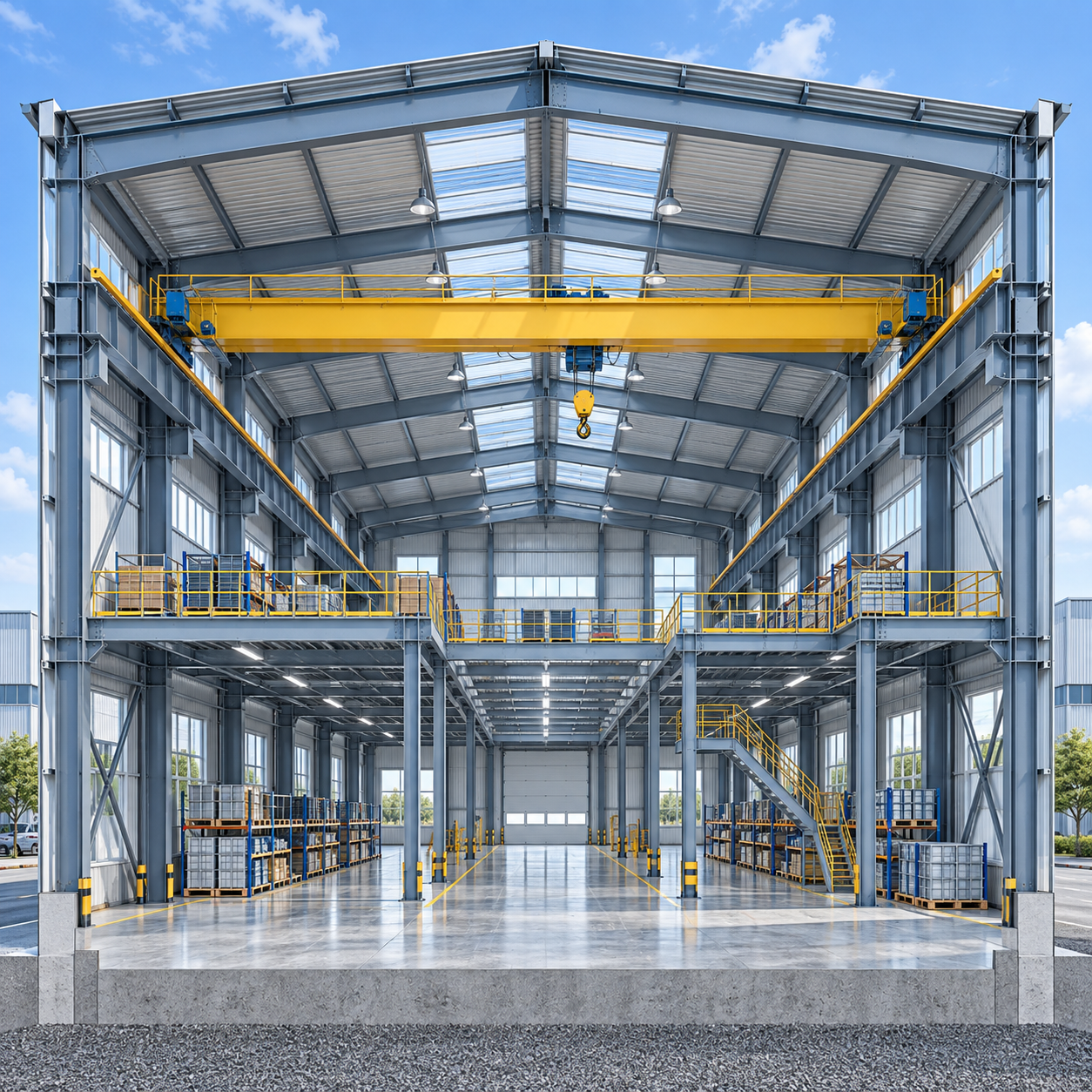
Planning Steel Building Design Around Crane Loads, Mezzanines, and Clear Height
Effective Steel Building Design starts with a simple question: what must happen inside the building every day? That sounds obvious, yet many projects still begin with a preferred span, an attractive eave height, or a rough floor area. The operational requirements arrive later, when equipment suppliers, process engineers, or tenants ask where the crane runway will sit, how high a conveyor needs to pass, or whether a mezzanine can support dense pick-and-pack activity.
By that point, the structural grid may already be working against the operation. Columns may conflict with material flow. Roof members may not have been designed for concentrated suspended loads. Foundations may be too light for crane reactions. Raising the roof or adding a mezzanine after the primary frame is detailed can be done, but it is rarely the economical route.
For project managers, the practical task is not to become a structural engineer. It is to freeze the right operational inputs early enough that the structural engineer, steel fabricator, equipment vendor, and civil team are designing the same building. Crane capacity, hook approach, mezzanine use, clear height, equipment loads, and expansion plans should be treated as connected decisions rather than separate packages.
Why Crane Requirements Change the Whole Frame
An overhead crane is not just an item on an equipment schedule. It changes the behavior of the building. The crane bridge transfers vertical wheel loads, lateral surge forces, braking effects, and impact-related actions into the runway beams and then into the columns. Those forces affect column size, column bracing, knee details, base plates, anchor bolts, and the foundation design.
A common early-stage mistake is to specify only crane capacity: for example, “10-ton crane required.” Capacity alone is insufficient. The design team also needs the crane span, runway length, wheel spacing, crane self-weight, hook lift, duty classification, travel speed where relevant, and whether one or two cranes may operate in the same bay. The supplier’s wheel-load chart is usually more useful to the structural designer than the nominal lifting capacity.
The required hook height also needs careful translation into building height. A crane serving a tall machine, a mold handling area, or a high-bay storage operation may require more than a generous-looking eave. The real check is the vertical stack: finished floor level, lifted load height, sling and hook dimensions, crane clearance, runway beam depth, roof steel depth, and roof service zones. If the building has roof-mounted ducts, sprinklers, cable trays, or conveyors, the clearance stack becomes tighter still.
Column spacing is another trade-off. Wider bays can reduce the number of foundations and improve internal circulation, but crane runway beams may become heavier or deeper. Tighter bays may give better runway support but can obstruct equipment positioning, vehicle aisles, and racking layouts. There is no universal “best” spacing. The right choice comes from testing the crane runway and process layout together before the frame is released for detailing.
Do not overlook horizontal crane forces
Vertical reactions are easy to understand because they resemble ordinary gravity loads. Horizontal loads are often where coordination problems show up. Crane acceleration, braking, skewing, and trolley movement introduce longitudinal and transverse actions. These must have a clear load path through bracing, portal frame action, diaphragm behavior, and foundations. A crane runway cannot be treated as an isolated steel member attached to an otherwise ordinary warehouse frame.
This is especially important where a project intends to install the crane later. “Crane-ready” should be defined in writing. Does it mean the columns and foundations are designed for a future crane? Are runway brackets included? Is the roof bracing arrangement compatible with the runway system? Has allowance been made for future electrical feeds and maintenance access? Without these answers, crane-ready can become a vague phrase with expensive consequences.
Mezzanines Need a Use Case, Not Just a Load Figure
A mezzanine often looks like an efficient way to create more usable area without enlarging the building footprint. It can be exactly that, but its design should start with how the level will be used. Office space, light storage, manual picking, automated sortation, maintenance access, and dense pallet handling do not place the same demands on the structure.
Floor live load is only one part of the decision. Point loads from shelving legs, autonomous equipment, machinery supports, compactors, or conveyor frames can control local beam and slab design. Forklift use on a mezzanine may introduce a much more demanding structural and safety problem than pedestrian picking. Vibration and deflection can matter even when strength calculations are satisfactory. A floor that is structurally safe but noticeably bouncy is not a good working platform for scanners, conveyors, precision equipment, or staff who spend full shifts on it.
The support strategy also matters. A free-standing mezzanine can simplify some interfaces, but it consumes floor space with its own columns and footings. Integrating mezzanine members into the primary steel frame can create a cleaner layout and reduce duplicate structure, provided the coordination is done before fabrication. Trying to bolt a large mezzanine onto completed portal frames may create connection, bracing, fire protection, and access conflicts that were avoidable at the planning stage.
Egress should be discussed alongside structure. Stair locations, travel routes, handrails, guardrails, fire separation, sprinkler coverage, and maintenance escape paths need local-code review. It is not enough to reserve a rectangle on a general arrangement drawing and label it “future mezzanine.” The area below it may need to remain open for conveyor transfers, packing stations, forklift lanes, or electrical rooms.
Clear Height Is More Than Eave Height
Clear height is frequently misunderstood because eave height is easy to state and compare. In operation, however, the useful height is measured below the lowest obstruction. That could be the haunch of a portal frame, a roof brace, a crane runway, a sprinkler main, a ventilation duct, a lighting line, or a suspended conveyor.
For a warehouse, clear height may determine rack configuration and lift-truck selection. For manufacturing, it may govern equipment installation, maintenance removal paths, and crane hook travel. In fulfillment operations, the question becomes more layered: how much height is needed for storage, multi-level picking, sortation, sprinkler clearance, and maintenance access at the same time?
Increasing the eave height late in the process affects more than the columns. It can alter wind loading, bracing demand, wall cladding quantities, access equipment needs during erection, fire strategy, and mechanical service routing. On sites with weak soils, higher columns and larger overturning effects can also influence the foundation solution. The cheapest way to obtain extra clear height is usually to define the required clear height correctly before the primary frame is designed.
There is also a useful distinction between “clear height everywhere” and “clear height where it matters.” Some operations need uninterrupted volume through the center of the building but can tolerate lower zones along sidewalls for offices, utilities, or low-level storage. Others need consistent clearance across a wide racking field. Mapping those zones can prevent the project from paying for height that has no operational value.
When Material Handling Equipment Becomes Part of the Building
Modern logistics buildings make the boundary between equipment design and building design less clear. Conveyors, sorters, monorails, cable trays, and service platforms are often suspended from the roof structure. Their loads should not be averaged into a generic roof live load. They need to be identified as actual point loads at known nodes, with load magnitude, location, support condition, and movement or vibration characteristics confirmed by the equipment supplier.
This is particularly relevant for an E-Commerce Fulfillment Center, where the material-handling layout may dictate the building grid more strongly than the exterior envelope. Typical clear spans may range from 24 to 48 m, with eave heights around 9 to 15 m under the haunch, but those ranges are only a starting point. Column spacing in the 8 to 12 m range may need to follow the sorter footprint, transfer lines, and dock arrangement rather than a standard warehouse module.
A sorter that deflects beyond its operating tolerance can disrupt parcel flow well before the roof structure approaches a strength limit. That is why reinforced hangers, local rafter strengthening, purlin checks, and accurately fixed connection positions are so important. In a coordinated Tekla model, equipment interface points can be resolved before shop drilling and fabrication. This is far more dependable than asking site crews to create new holes or weld ad hoc supports after the steel is erected.
Mezzanine-supported pick modules raise the same issue from below. In busy pick-and-pack zones, floor loading can be substantially higher than ordinary office or light-storage assumptions; some layouts may require design values up to 50 kN/m². The final value must come from the operation and applicable local requirements, not from a generic warehouse specification. Roof design also needs to account for ordinary roof actions alongside suspended conveyor loads, which may be concentrated and unevenly distributed.
A Coordination Sequence That Avoids Rework
The most reliable Steel Building Design process is not necessarily the longest one. It is the one that gets the critical information in the right order. Before approving the primary structural concept, assemble a coordinated set of operational inputs:
- Crane supplier data, including wheel loads, runway geometry, hook height, operating conditions, and future crane provisions.
- Mezzanine plans showing intended use, equipment footprints, rack legs, floor openings, stairs, and anticipated service routes.
- A clear-height diagram that identifies the lowest permissible elevations in every operating zone, not only the nominal eave height.
- Material-handling drawings that show suspended loads, support nodes, maintenance clearances, and any later installation sequence.
- Site information covering wind, snow where applicable, seismic requirements, soil conditions, drainage levels, and local authority expectations.
- Expansion assumptions: additional cranes, a second mezzanine level, extended conveyor lines, solar equipment, or future wall openings.
This package lets the structural team establish load paths before steel quantities are optimized. It also gives the project manager a basis for comparing alternatives honestly. A lower-cost initial frame may not remain lower-cost if it forces separate support steel, heavier retrofit foundations, downtime, or compromised equipment layout later.
Fabrication Quality and Documentation Matter at the Interfaces
Once the loading and geometry are settled, the design still has to survive the transfer from model to fabrication and site erection. For export projects, this means matching steel grades, connection details, coating requirements, and inspection records to the project specification. Q355B and Q235B are commonly used under GB standards, while S355JR, S275JR, or ASTM A572 Gr.50 may be selected where the design basis calls for them. Grade selection should follow the engineer’s requirements and availability of compliant material documentation, not a simple preference for a familiar designation.
A manufacturer with large-scale production capability can help reduce interface risk when the structural model, shop drawings, CNC cutting, welding, packing plan, and erection documents are managed as one chain. For example, a Chinese prefabricated steel building manufacturer operating a 120,000 m² plant with annual output capacity of 100,000 tonnes may have the production depth to handle major industrial packages, but project success still depends on disciplined drawing review and clear approval responsibilities.
For projects delivered across different markets, ISO, CE, AS/NZS, and ASTM-related requirements should be checked against the actual contract and local design code. Certifications support a quality system; they do not replace project-specific engineering. The same caution applies to coatings. Hot-dip galvanizing, epoxy zinc-rich paint systems, duplex protection, and marine-grade coatings each have different implications for exposure conditions, connection detailing, transport damage, and site touch-up.
The Decision to Make Before Steel Is Ordered
The key planning decision is whether the building is being designed around the operation or whether the operation will be forced to fit an already-defined shell. In straightforward storage buildings, a conventional portal frame may allow considerable flexibility. In crane-served workshops, automated fulfillment centers, and multi-level distribution facilities, that flexibility narrows quickly.
Before approving the steel package, ask for one coordinated review of crane data, mezzanine loading, equipment support points, clear-height zones, service routes, and foundations. If any of those items remains “to be confirmed,” identify whether it can change the primary frame. That single conversation is usually more valuable than trying to solve the same issue later through site modifications, heavier connections, or rushed redesign.
We are more than happy to serve you here. If you have any question, please feel free to contact us.