
News center
Related Posts
- ▶ Prefab vs. Conventional Warehouse Construction: Comparing Timelines
- ▶ Planning a Prefab Warehouse: Clear Span, Height and Loading Bays
- ▶ How Long Does It Take to Build a Commercial Steel Building?
Online Message
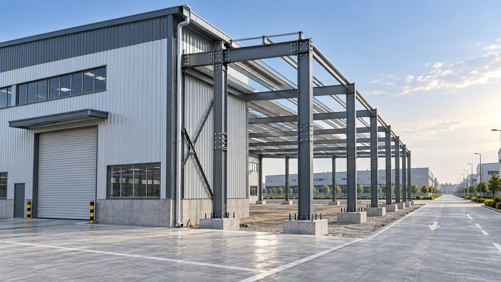
Future expansion is easiest when the original steel frame already contains a logical place for the next frame, roof extension, service connection, and traffic route. The lowest-disruption approach is usually to extend the building from a planned end wall or side bay while keeping the existing production, storage, or commercial area operational. That outcome depends on decisions made before fabrication drawings are released: grid geometry, column and foundation capacity, bracing layout, roof drainage, wall interfaces, and utility distribution all need to support a defined expansion direction.
A Steel Building Design does not need to be oversized everywhere to remain expandable. Reserving capacity indiscriminately adds steel weight and foundation cost without necessarily making a later connection practical. A better basis is a documented expansion scenario: the anticipated footprint, intended use, required clear height, likely floor loads, material-handling equipment, vehicle circulation, and the period during which the existing building must remain in service. These inputs distinguish a building that can physically become larger from one that can be extended without major reconstruction.
Start with the direction and form of growth
End-wall extension is often the cleanest option for a single-span warehouse or industrial hall. The new building bays continue the original longitudinal grid, and the former end wall becomes an internal separation that can be removed in stages. This arrangement works well when the site has adequate length, truck movement can be redirected during construction, and the original roof drainage can be extended or reconfigured without trapping water at the connection.
Side expansion creates different structural questions. Adding bays along one eave may require a new column line, altered guttering, relocation of downpipes, and a review of how the original lateral system behaves after the wall is opened. A side extension is attractive where site depth is available but the existing end wall contains loading docks, process equipment, or a fire separation that should remain undisturbed. It is less straightforward when the original frame relies on that side wall for bracing or when the expansion would conflict with underground utilities.
Vertical growth should be evaluated separately from horizontal expansion. A roof intended only for weather protection is not automatically suitable for a future mezzanine, suspended equipment, solar installation, or accessible service deck. Column axial load, base connection forces, frame deflection, and fire-protection requirements all change with added levels. Treating “space above the floor” as uncommitted future capacity is a common source of false flexibility.
Set a structural grid that can continue
Bay spacing establishes the rhythm of a steel building. When future bays follow the original spacing, fabrication details, purlin lengths, roof panels, cladding modules, and floor-joint locations are easier to coordinate. Repetition also reduces the number of special transition members required at the interface. The preferred grid is not necessarily the widest possible bay. A wide bay may reduce the first-stage column count, yet it can produce heavier rafters, deeper members, larger deflections, and more demanding lifting requirements during a later extension.
The expansion grid should be coordinated with the operational layout rather than selected from frame efficiency alone. Racking aisles, crane runways, dock positions, vehicle lanes, machine foundations, and fire access may impose dimensions that do not align with the most economical frame module. A workable scheme identifies where structural columns can remain without interrupting those functions after the building grows.
Clear height deserves the same discipline. Extending a low original eave height beside a later high-bay zone can create awkward roof steps, complicated gutter details, and internal material-flow constraints. Conversely, building the whole first phase at a high clear height merely to anticipate a possibility may be unjustified. The decision should follow the likely future process, especially equipment height, rack configuration, lifting paths, and ventilation requirements.
Use a removable end-wall strategy
An expandable end wall needs more than demountable cladding. The primary frame, secondary steel, wall bracing, door framing, eave details, insulation, and drainage must be considered as a package. If a rigid end wall later becomes an internal line, its wind bracing may need replacement by roof-plane bracing, portal action, or braced bays elsewhere. Removing cladding panels without addressing that load path can leave the existing structure temporarily unstable.
Bolted splices at the planned extension line simplify site work because new members can connect to prepared interfaces. Connection geometry should allow erection tolerances and access for tightening bolts after adjacent panels are installed. A detail that is easy to model but leaves no room for tools, temporary supports, or lifting slings can slow the later phase considerably.
Reserve foundations where the future frame needs them
Foundation planning is often the point at which expansion flexibility is lost. A future steel column requires more than a marked location on a drawing; it needs a foundation designed for anticipated vertical reactions, uplift, shear, and overturning effects. Nearby existing foundations also need sufficient separation and compatible levels so that excavation for the new work does not undermine them.
There are two sound approaches. The first installs future footings, starter bars, or base plates during the initial phase and protects them until required. This avoids later excavation near active operations, but exposed or buried components need reliable location records and corrosion protection. The second designs the current foundations and grade beams with a planned tie-in arrangement, leaving the later foundations to be constructed when the extension scope is confirmed. This reduces initial expenditure but demands clear information about soil conditions, drainage, buried services, and access for piling or excavation equipment.
Foundation reserve capacity must be interpreted carefully. Increasing footing size does not automatically solve later expansion. The controlling condition may be column uplift from wind, differential settlement between old and new work, an existing slab that was never designed to transfer column loads, or a change from light storage to concentrated equipment loading. Geotechnical information should remain available with the as-built structural records, including founding level, groundwater observations, soil improvement details, and any restrictions on adjacent excavation.
Keep lateral stability adaptable
Braced bays are efficient, but their position matters when walls may be opened for circulation or future building bays. Cross bracing placed at an intended expansion face can obstruct doors, conveyors, or vehicle routes and will have to be relocated before the opening is created. Locating primary braced bays away from probable connection zones often gives a more durable expansion path.
Rigid-frame action and braced-frame action should not be treated as interchangeable. A portal frame may carry transverse loads through moment connections at its columns and rafters, while longitudinal forces are often resisted through roof bracing and vertical braced bays. Extending the length of the building changes the distribution and accumulation of longitudinal actions. New bays require a complete load-path review from roof diaphragm through bracing, columns, foundations, and ground.
For buildings with cranes, future expansion must also account for surge forces, runway alignment, rail tolerances, and the possibility that lifting equipment will extend into the new area. A frame that can support a crane runway in the first phase does not necessarily permit a simple runway extension. Differential settlement and frame deflection can affect rail continuity, making early coordination more valuable than adding isolated steel later.
Design roof, cladding, and drainage as connection systems
Water management frequently creates the most disruptive expansion work. A roof extension changes catchment area, gutter capacity, downpipe locations, overflow routes, and the interface between old and new roof sheets. The detail must prevent water from being driven beneath laps during wind, while allowing for thermal movement and construction tolerances. A roof step can be practical, but it needs a deliberate flashing arrangement and a route for drainage that remains accessible for cleaning.
Matching the original roof pitch and cladding profile may simplify the appearance, though exact replication is not always necessary or available years later. What matters more is whether the transition can be weather-tight, maintainable, and structurally supported. Store panel profile data, coating information, fastener type, insulation thickness, purlin spacing, and flashing details with the building records. These small specifications are difficult to reconstruct after the original procurement package has been dispersed.
Wall systems need an equally clear boundary. Future openings should avoid cutting through unverified load-bearing rails, fire-rated assemblies, or services concealed behind liners. Where thermal performance matters, an extension joint needs continuity in insulation and air sealing; otherwise, a nominally weatherproof connection can still create condensation-prone zones near the old external wall.
Route utilities so they can branch without shutdowns
Electrical, water, compressed air, drainage, fire protection, communications, and process lines should have accessible expansion points rather than terminating inside finished walls or beneath fixed equipment. Main distribution routes are often best located along a corridor, service spine, or perimeter where isolation valves, spare conduits, cable trays, and inspection access remain available. The route must suit actual maintenance access, not merely appear clear on a coordination drawing.
Reserve space is more useful than reserve equipment. Installing capacity that will not be used for years may create maintenance obligations and compatibility problems. In contrast, allowing room for future switchgear, pipe branches, sleeves, penetrations, and support brackets preserves options while limiting dormant components. The expected future load still needs to be stated, because a nominal spare conduit does not resolve transformer capacity, pump duty, drainage fall, or fire-water hydraulic demand.
Floor drainage and slab joints require particular care. An extension with a different finished floor level can disrupt forklift movement and create ponding at doorways. If the building will be extended from an end wall, locate underground drainage so it does not cross the proposed foundation line or force later trenching through high-traffic slabs. Equipment pads, pits, and anchor zones should be mapped as accurately as columns.
Plan the construction sequence before first-phase handover
Expansion-ready design is incomplete without an erection concept for the future phase. The proposed work area needs a crane setup zone, delivery route, safe material storage, and a method for keeping rain out when sections of the original envelope are removed. Long steel members may be difficult to unload in a constrained operating yard even when the structural design is straightforward.
Temporary stability also deserves explicit drawings. Opening a braced wall, removing rails, or disconnecting roof sheeting can change the behavior of the remaining structure during construction. The sequence should identify temporary bracing, lifting points, restricted areas, and the order in which new steel is connected before old elements are removed. This is especially important where continued operations prevent a full building shutdown.
Modular thinking applies beyond building frames. Temporary site access can need the same flexibility during a phased extension, particularly where construction traffic must cross drainage channels, unstable ground, or a route that cannot be blocked for long. Standardized, reusable truss systems such as a Steel Bridge Prefab Steel Truss Structure Bridge Design for Sale can be evaluated for temporary crossings where span, traffic load, deck width, foundation support, and local site requirements have been confirmed. The relevant lesson for building expansion is the value of connection points and repeatable components, not the assumption that every modular product suits every access condition.
Maintain an expansion record, not only an as-built drawing set
Future work depends on information that is often missing when the need to expand finally arises. Retain structural calculations, member schedules, connection drawings, bolt grades, weld records where relevant, coating specifications, foundation locations, survey benchmarks, underground-service drawings, and approved changes made during construction. Mark planned expansion interfaces clearly in the record set rather than relying on a general note in an early design package.
A useful record also states the assumptions behind reserved capacity. For example, a prepared connection may have been intended for a roof-only extension, not for a crane-loaded bay; a spare electrical route may have been sized for lighting and small power, not process equipment. This prevents a later team from treating every visible provision as unrestricted capacity.
The most durable expansion strategy is a controlled boundary between what is built now and what can be added later. When that boundary is coordinated across frame, foundations, enclosure, utilities, and construction access, the later phase becomes a planned assembly task rather than a series of removals, investigations, and compromises.
We are more than happy to serve you here. If you have any question, please feel free to contact us.