
Related Posts
- ▶ Prefab vs. Conventional Warehouse Construction: Comparing Timelines
- ▶ Planning a Prefab Warehouse: Clear Span, Height and Loading Bays
- ▶ How Long Does It Take to Build a Commercial Steel Building?
Online Message
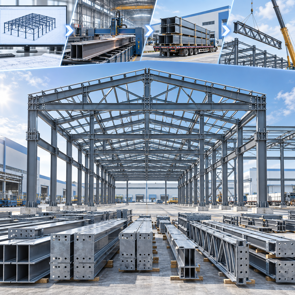
Steel Structure Design and Fabrication: Why the Process Must Be Treated as One Chain
A steel building rarely fails because one person made one dramatic mistake. More often, trouble begins with a small disconnect: a design assumption that was not carried into the shop drawings, a connection detail that cannot be accessed during erection, a coating requirement omitted from the purchase order, or a shipment sequence that does not match the site schedule.
That is why Steel Structure Design and Fabrication should be understood as a connected process rather than two separate services. Engineering defines how a structure carries load. Detailing translates that intent into manufacturable pieces. Fabrication turns the drawings into traceable components. Logistics and site assembly then prove whether all those decisions can work together in the real world.
For commercial buildings, industrial plants, warehouses, transport facilities, and large-span public structures, this chain has a direct effect on safety, cost certainty, construction speed, and long-term maintenance. Buyers researching prefabricated steel structures are often comparing suppliers on tonnage capacity or quoted price. Those factors matter, but the more useful question is: how reliably can the supplier take a project from design information to an erectable steel frame?
The Project Starts Before the First Steel Plate Is Cut
The initial structural design phase establishes the building’s load path and overall behavior. Engineers review architectural drawings, site conditions, intended use, loading criteria, and local code requirements. Dead loads, imposed loads, wind, snow, seismic action, crane loads, equipment loads, and temperature effects may all influence the final member sizes and connection strategy.
At this point, the building is not yet a list of beams and columns. It is a structural system. A portal frame for a logistics warehouse behaves differently from a multi-storey braced frame, while a roof over an exhibition hall may call for a three-dimensional system rather than conventional trusses. The selected system should reflect span, clear-height requirements, future expansion plans, roof and wall cladding, service penetrations, and the available erection space.
Material selection also belongs early in the conversation. Common grades include Q235B and Q355B under Chinese standards, S275JR and S355JR under European standards, and ASTM A572 Grade 50 for projects using American specifications. These grades are not interchangeable merely because their strength levels look similar on paper. The design basis, certification requirements, welding procedure, and project specification all need to align.
A good structural package identifies more than member sizes. It should state the applicable design standard, connection philosophy, corrosion-protection system, tolerances, bolt grades, welding requirements, and any special inspection needs. Where an overseas project requires EN 1993, AISC principles, AS/NZS provisions, or a locally adopted standard, this should be clarified before detailing begins—not after fabricated steel is ready for shipment.
Shop Drawings Are the Bridge Between Engineering and the Workshop
Shop drawings are often mistaken for a clerical output. In reality, they are among the most consequential documents in steel structure design and fabrication. They convert the engineer’s design drawings into instructions that fabrication teams, quality inspectors, freight planners, and site crews can act on.
A complete shop drawing set normally includes member marks, section sizes, cut lengths, plate dimensions, hole locations, weld symbols, bolt schedules, connection assemblies, material grades, and coating notes. Erection drawings add another layer: grid lines, elevations, assembly sequence, bracing locations, temporary stability requirements, and reference dimensions for the installation team.
Modern detailing commonly uses a coordinated 3D model. Platforms such as Tekla can help generate accurate member lists and connection details from the same model used for clash checks and erection planning. Still, software does not replace engineering judgement. The detailer must ask practical questions: Can a welder reach the joint? Is there sufficient clearance for bolt tightening? Will a long girder fit the transport route? Can the site crane lift and rotate the assembly safely?
Approval discipline matters here. When clients, architects, consultants, and manufacturers work from different drawing revisions, errors spread quickly. A controlled process should identify revision numbers, document approval status, and make clear which drawings are “for review,” “for construction,” or “as built.” A late change to a roof opening, column position, or equipment support can affect far more than one sheet of drawings.
Connection Details Deserve Extra Attention
Connections are where calculated forces become physical reality. Bolted connections offer speed and easier site assembly, while welded connections may provide compact geometry or satisfy specific design demands. Many projects use both. The right choice depends on load, accessibility, fatigue considerations, erection method, inspection capability, and local practice.
It is not enough for a connection to be structurally adequate. It must also be buildable and inspectable. For example, bolts must have installation clearance, splice plates must be oriented correctly, and field welds should be minimized when weather, high-level work, or quality control makes them difficult. Designing for fabrication and erection at the outset often prevents expensive adjustments later.
From Certified Material to Identifiable Components
Once approved drawings and material take-offs are released, procurement and production can begin. Reliable fabrication starts with steel from qualified mills and with documentation that preserves material traceability. Mill certificates, heat numbers, receiving inspection records, and identification marks allow the manufacturer to connect finished members back to their source material.
In a controlled factory workflow, plates and sections are checked before processing. Steel may then be CNC cut, drilled, beveled, bent, assembled, welded, straightened, and prepared for surface treatment. The exact route changes with the component: a built-up tapered column is produced differently from an H-section beam, tubular truss member, or machined spherical node.
Welding deserves particular care because it affects both strength and durability. Welding procedures should suit the material grade, joint type, thickness, and specified performance. Depending on the project, production may use automatic submerged-arc welding for long, repeatable seams and manual or semi-automatic processes for more complex details. Visual checks are essential, but they may not be sufficient for critical joints. Ultrasonic testing, magnetic particle testing, or other non-destructive examination methods can be specified to verify weld integrity.
Dimensional control is just as important. A member that is slightly out of tolerance may seem harmless in the workshop but can create a serious alignment problem several floors above ground. Fabricators therefore inspect overall length, camber, hole position, flange alignment, weld profile, and assembly geometry against approved drawings and applicable tolerances.
Surface Protection Is a Design Decision, Not a Final Cosmetic Step
Steel’s durability depends heavily on its exposure environment and protective system. A dry inland warehouse may require a different solution from a coastal terminal, chemical-processing facility, or building with frequent condensation. The best coating choice is therefore not automatically the thickest or most expensive one; it is the system compatible with the service environment, expected maintenance plan, and project specification.
Options can include shop-applied paint systems, hot-dip galvanizing, or duplex protection that combines galvanizing and paint. Marine-grade or high-corrosion environments often need closer attention to surface preparation, edge treatment, coating thickness, handling damage, and repair procedures after site installation.
Coating work should follow defined stages: surface preparation, environmental checks, application, dry-film-thickness measurement, curing, and final inspection. If field welding or bolting will damage protected areas, touch-up materials and procedures should be identified in advance. Leaving this question to the last week of construction can undermine an otherwise well-made steel package.
Large Spans Change the Conversation
When architects need broad, column-free interiors, conventional framing can become heavy or visually intrusive. Stadium roofs, exhibition buildings, airport halls, and industrial facilities with irregular plan shapes may benefit from a space-frame approach. In these systems, members and nodes form a double-layer grid that distributes load in several directions rather than through a single line of beams.
A Space Frame Structure System can be designed for spans of approximately 30 to 100 metres, with grid modules typically in the 2 to 4 metre range and grid depths around 1.5 to 3 metres, subject to project loading and geometry. Bolted-sphere and welded-sphere node arrangements are common. With bolted-sphere systems, accurately prepared tubular members can often be screwed into pre-machined nodes on site, reducing the need for field welding.
The advantage is not simply “big span.” The geometry must be coordinated carefully. Member lengths, node angles, support conditions, roof drainage, skylights, suspended services, and cladding interfaces all affect the final result. Structural analysis may be carried out in software such as PKPM, 3D3S, Midas, or SAP2000, while shop detailing links the calculated geometry to workshop production.
Factory Fabrication Should Make Site Assembly More Predictable
Prefabrication moves much of the difficult work from an exposed construction site into a controlled production environment. That does not eliminate site risk, but it can reduce uncertainty when fabrication, packing, and erection planning are coordinated.
Before dispatch, components should be marked clearly and packed according to the erection sequence where practical. Small connection plates and bolts need robust labeling; they are easy to misplace and disproportionately important when a crew is waiting for one missing item. Long members must be supported correctly to avoid distortion during transport, while containers and break-bulk shipments require different planning.
For export projects, the documentation package can be as important as the steel itself. It may include packing lists, marking plans, material certificates, inspection records, coating reports, assembly drawings, and shipping documents. A manufacturer with large-scale capacity may be able to produce significant tonnage, but buyers should also confirm its ability to manage these project-specific records consistently.
China-based manufacturers serving international markets often work with project requirements across ISO, CE, AS/NZS, ASTM, EN, and other standard frameworks. Certifications are useful evidence of a controlled system, yet purchasers should still verify whether the supplier’s quality plan, welding qualifications, inspection scope, and design references match the individual project—not merely the company brochure.
What Happens on Site: Assembly, Stability, and Tolerance
Site assembly begins with foundations and anchor bolts. Before the first column is erected, the team should verify grid dimensions, elevations, anchor-bolt position, and base-plate compatibility. Steel can only be installed as accurately as the supports allow.
The erection sequence is then planned around temporary as well as permanent stability. A frame may be stable once all bracing, roof members, and diaphragm elements are complete, but it can be vulnerable during intermediate stages. Temporary bracing, crane positioning, lifting points, weather monitoring, and exclusion zones are part of the construction method—not optional housekeeping.
Bolted connections should be installed using the specified method, particularly where high-strength bolts require controlled tightening. Field changes should not be improvised. If a hole does not align or a member does not fit, the cause may be survey error, incorrect orientation, transport damage, drawing mismatch, or fabrication tolerance. The correct response is documented investigation and approved rectification, not forced assembly.
A Practical Checklist for Evaluating a Steel Structure Supplier
For an information-stage buyer, the goal is not to become a fabrication expert overnight. It is to identify whether a prospective manufacturer has a process that protects the project from avoidable surprises. Ask for clear answers to these points:
- Which structural design codes and material standards can the team work with?
- Will the supplier provide design support, shop drawings, erection drawings, and a coordinated 3D model where needed?
- How are mill certificates, member marks, and material traceability controlled?
- Which welding procedures and non-destructive tests are available for the project’s critical joints?
- What inspection hold points exist before coating and shipment?
- How will components be packed, labeled, and sequenced for export and site assembly?
- Can the supplier provide localized erection manuals, assembly guidance, or site supervision when the project requires it?
The lowest steel weight or lowest unit price is not always the lowest project cost. Rework, delayed shipping, missing components, unclear drawings, and difficult field welding can quickly consume an apparent saving. A well-managed steel package creates value by making the construction process easier to plan, inspect, and complete.
The Real Measure of Steel Structure Design and Fabrication
The finished building is the final test. Beams must meet columns as intended. Bolt holes must align. Coatings must withstand their environment. The roof system must receive its cladding without improvised adjustments, and the structure must perform under the loads it was designed to carry.
That outcome depends on continuity—from early engineering choices through shop detailing, factory controls, shipment preparation, and disciplined site erection. For anyone sourcing prefabricated steel structures, understanding this full chain is more valuable than focusing on fabrication alone. Steel is a material; a successful structure is the result of coordinated decisions made long before the first truck arrives on site.
We are more than happy to serve you here. If you have any question, please feel free to contact us.