
Related Posts
- ▶ Prefab vs. Conventional Warehouse Construction: Comparing Timelines
- ▶ Planning a Prefab Warehouse: Clear Span, Height and Loading Bays
- ▶ How Long Does It Take to Build a Commercial Steel Building?
Online Message
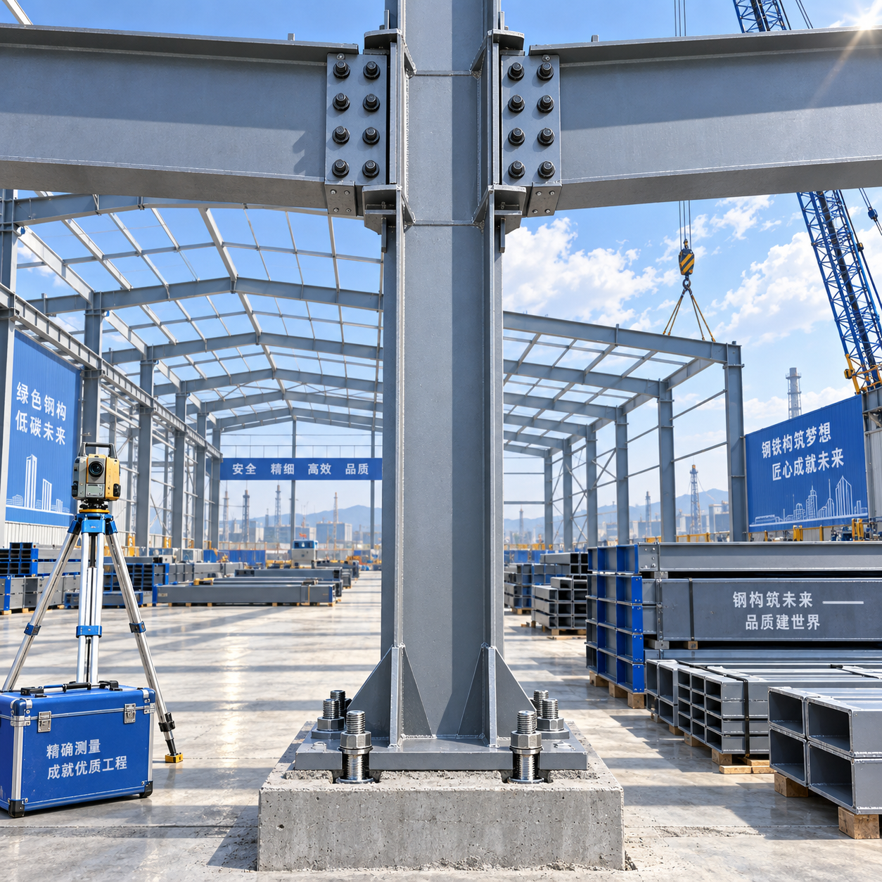
Fabrication tolerances are often treated as a workshop issue until the first column refuses to align with its base plate, a roof truss arrives with holes that will not match, or a bracing bay needs force to close. By then, a few millimetres of variation can turn into lost crane time, unplanned field modifications, delayed inspections, and avoidable safety exposure.
For quality and safety managers, the connection between Steel Structure Design and Fabrication, dimensional control, and erection performance deserves attention long before steel reaches site. Tolerance is not simply a number on a drawing. It is the agreed amount of dimensional variation that the design, fabrication process, connection detailing, foundations, and erection sequence can safely absorb. When that agreement is unclear or poorly managed, site fit-up becomes unpredictable.
This article examines how fabrication tolerances affect steel structure fit-up and installation speed, where tolerance problems usually originate, and what practical controls help prevent a small dimensional deviation from becoming a major site issue.
Fit-Up Begins with the Tolerance Strategy, Not the First Bolt
Steel erection is an assembly process. Columns must land on foundations, beams must meet columns, secondary members must follow the primary frame, and roof or wall systems must align with the steel that supports them. Every interface has a permissible range of movement, but those ranges are not unlimited.
A structure may include tolerance requirements for:
- member length, straightness, sweep, and camber;
- column height and base-plate geometry;
- bolt-hole diameter, spacing, and group position;
- plate thickness, squareness, and edge preparation;
- weld size, weld location, and distortion after welding;
- assembly dimensions between connection points;
- coating thickness where it affects bolted or mating surfaces.
Each item may appear manageable on its own. The difficulty is cumulative tolerance. A base plate can be within its permitted variation, anchor rods can be within their setting tolerance, and a column may also comply with its fabrication tolerance. Yet the combined condition can still leave too little clearance for practical erection. This is especially relevant at fixed connections, closely spaced anchor rods, long rigid frames, and structures with repeated bays.
Good Steel Structure Design and Fabrication therefore considers the full chain of variation. Designers define the functional intent; detailers convert it into workable geometry; fabricators control the manufactured dimensions; civil teams position anchors and foundations; erectors establish the final line, level, and plumb. A tolerance plan that ignores any one of these parties is incomplete.
Why a “Minor” Fabrication Deviation Can Slow Installation
Installation speed is rarely reduced by one dramatic failure. More often, it is lost in small interruptions: checking a mismatch, waiting for an engineer’s response, loosening a connection, adding packers, reaming holes, re-surveying a gridline, or moving a crane while a crew resolves an unexpected interface. Those interruptions disrupt the planned erection rhythm.
Consider a portal-frame building. If column centre distances vary from the released geometry, rafters may not seat naturally at their end-plate connections. Crews may try to pull members into place with bolts, chain blocks, or the crane. This approach is risky. It can introduce unintended stresses, damage coatings, distort connection plates, or create a partially stabilized frame that does not match the design assumptions.
Even where bolts can be installed, forced fit-up may conceal a deeper issue. The frame could be carrying residual stress, the roof purlin line could be displaced, or cladding rails may later require site trimming. Problems propagate downstream: what begins as a connection issue becomes a roofing, enclosure, drainage, or equipment-installation issue.
The Three Interfaces That Deserve the Closest Control
1. Foundation-to-steel interfaces
Anchor rods are among the most sensitive interfaces in an erection package because they are controlled by a different work scope from the fabricated steel. A well-made column cannot compensate indefinitely for anchor rods that have shifted during concrete placement.
Before fabrication is completed, the project team should confirm the governing grid, datum level, anchor-rod setting template, rod projection, base-plate hole configuration, grout allowance, and any permitted adjustment method. The fabricator’s base-plate drawing and the civil anchor layout should be checked against the same issued-for-construction information, not against separately revised files.
On site, an as-built anchor survey before steel delivery provides valuable warning. It allows the team to identify isolated deviations, verify whether adjustment is permitted, and plan an engineered remedy before cranes and erection crews are committed.
2. Primary-frame connections
Moment connections, portal-frame knees, truss splices, and rigid end plates require more discipline than simple shear connections. Their geometry controls structural behaviour as well as ease of assembly. Hole patterns, flange spacing, plate flatness, weld-induced distortion, and member orientation all need to be checked before dispatch.
For bolted connections, the specification should clearly state the hole type and the intended installation method. Standard, oversize, short-slotted, and long-slotted holes are not interchangeable site conveniences. Their use affects load transfer, detailing, inspection requirements, and sometimes the direction in which adjustment is possible. Enlarging holes in the field without approval may compromise the connection’s design intent.
3. Secondary steel and building envelope support
Purlins, girts, eave struts, sag rods, wall rails, and equipment supports are sometimes viewed as forgiving components. In reality, they set the geometry for roof panels, wall cladding, doors, ventilation equipment, and service runs. If they are fabricated or installed inconsistently, the building can look visually uneven even when the main frame is structurally acceptable.
This matters particularly in long agricultural and industrial buildings. A recurring bay error may become noticeable only after dozens of members are installed. Correcting it late is slower and more expensive than confirming repeat dimensions at the first assembled frame.
How Tolerances Should Be Read Against Applicable Standards
Quality managers should avoid assuming that one generic tolerance table governs every project. The relevant requirements may come from the contract specification, approved shop drawings, local building regulations, and the governing steelwork standard. Depending on the project location and contractual basis, teams may work with documents such as AISC 303, EN 1090 execution requirements, AS/NZS 5131, ASTM-related material and testing requirements, or other national standards.
The key question is not merely, “Does this member meet a published tolerance?” It is, “Does it meet the project’s stated standard and function correctly with the connected work?” A member can meet a broad manufacturing tolerance yet still be unsuitable for a particularly tight architectural, mechanical, or prefabricated interface.
Where a project uses ISO, CE, AS/NZS, ASTM, or similar compliance frameworks, document control is as important as physical measurement. The inspection team needs to know which revision governs, which acceptance criteria apply, who has authority to approve a deviation, and whether a nonconformance affects structural adequacy, erection feasibility, or both.
Fabrication Practices That Protect Installation Speed
The most useful tolerance controls occur at points where errors can still be corrected economically. Once a long welded assembly has been painted, packed, shipped, and lifted, options narrow quickly.
A disciplined fabrication workflow commonly includes the following controls:
- Drawing and model review: Check grid references, member marks, connection orientations, splice locations, and interfaces with foundations, cladding, and equipment before cutting begins.
- Material traceability: Maintain identification from incoming steel through cutting, assembly, welding, and dispatch, especially where different grades or thicknesses are used.
- Controlled fit-up before welding: Use jigs, fixtures, and verified datums to position plates and assemblies. Measure before weld shrinkage makes correction harder.
- Welding-sequence planning: Balanced weld sequencing, restraint methods, and suitable assembly practices reduce distortion in built-up columns, trusses, and connection plates.
- In-process dimensional checks: Do not rely only on final inspection. Check critical dimensions after cutting, tack assembly, welding, drilling, and trial assembly where appropriate.
- Marking and packing discipline: Clear member identification and erection-sequence packing reduce the chance of a correct part being installed in the wrong location.
Digital measuring tools, total stations, templates, and 3D model-based checking can improve confidence, but they do not replace clear inspection criteria. A precise instrument cannot solve an ambiguous datum or a drawing that leaves the adjustment strategy undefined.
Inspection Should Follow Risk, Not Habit
Not every dimension carries the same consequence. Measuring every non-critical feature with equal intensity can consume time without protecting the schedule. Conversely, overlooking a small number of critical interfaces can create severe erection problems.
A practical inspection and test plan should identify hold points for high-risk dimensions. These commonly include base plates, anchor-rod templates, major splice plates, truss panel points, repeated portal frames, crane runway brackets, and supports for process equipment. First-article inspection is particularly valuable when a project has many identical frames or modules. If the first unit is confirmed against the approved geometry, the team can stabilize the process before repetition magnifies an error.
Safety managers should also connect dimensional checks to the erection plan. If a connection is difficult to fit, workers may be tempted to work under suspended loads longer than planned, climb to make unapproved alterations, or remove temporary bracing prematurely. Dimensional quality is therefore part of fall protection, lifting safety, and temporary stability management—not a separate paperwork exercise.
A Relevant Example: Repeated Poultry-House Frames
In long-span livestock facilities, repeatability is not only a production advantage; it is a fit-up requirement. An Industrial Steel Poultry House may use spans from 15 to 36 m and typical lengths of 100 to 150 m, with recurring frames that support insulated roof and wall panels, tunnel-ventilation components, feed lines, drinkers, lighting, and, in some layouts, egg-handling systems.
In this setting, a slight inconsistency in frame spacing or eave level can affect more than roof alignment. It may interfere with side-wall air inlets, suspended equipment lines, panel joints, and the controlled internal environment required for poultry production. Galvanized steel and coatings suited to ammonia-rich conditions also require attention at bolted interfaces and repaired areas, so that fit-up corrections do not undermine corrosion-protection expectations.
For projects built as multiple houses to one repeated design, the best approach is to inspect the first completed frame assembly, compare it with the governing model and erection layout, and use the findings to confirm the remaining production run. A manufacturer operating controlled steel production lines can make repeatability more achievable, but only if fabrication records, packaging marks, and site survey information remain connected.
When a Mismatch Is Found on Site
The wrong response to a fit-up problem is often the fastest-looking response: force the member, burn a larger hole, cut a plate, or weld an improvised tab. These actions may create hidden structural, coating, and inspection consequences.
A safer response is to stop at the affected interface, maintain temporary stability, record the actual dimensions, and compare them with the approved drawings and applicable tolerance criteria. The project engineer or authorized design representative should determine whether the condition is acceptable as built, can be corrected with an approved adjustment, or requires a formal repair detail. Photographs, survey records, member marks, and a clear description of the erection stage make this decision much faster.
Root-cause review matters as well. Was the issue created by anchor setting, fabrication, shipping damage, incorrect member selection, coating buildup, or a drawing revision gap? Without that answer, the same mismatch can appear again in the next bay.
What Quality and Safety Managers Should Ask Before Release
Before a steel package leaves the factory—or before the erection team begins a critical sequence—several questions can expose tolerance risks early:
- Are fabrication tolerances explicitly tied to the project standard and approved drawings?
- Have critical connection dimensions been inspected using defined datums?
- Do base plates and anchor-rod layouts have a confirmed adjustment strategy?
- Have welded assemblies been checked for distortion after final welding?
- Are repeated frames or trusses subject to first-article verification?
- Does the erection sequence account for temporary bracing and the order in which fit-up must occur?
- Is there a controlled process for nonconformance reporting and engineering disposition?
Fast installation does not come from asking crews to work faster when steel arrives. It comes from delivering members that fit the intended geometry, providing enough controlled adjustment where real construction variation exists, and resolving exceptions before they become work at height. When tolerance management is embedded in Steel Structure Design and Fabrication, the site gains something more valuable than speed: a calmer, safer, and more predictable path from delivery to completed structure.
We are more than happy to serve you here. If you have any question, please feel free to contact us.