
News center
Related Posts
- ▶ Prefab vs. Conventional Warehouse Construction: Comparing Timelines
- ▶ Planning a Prefab Warehouse: Clear Span, Height and Loading Bays
- ▶ How Long Does It Take to Build a Commercial Steel Building?
Online Message
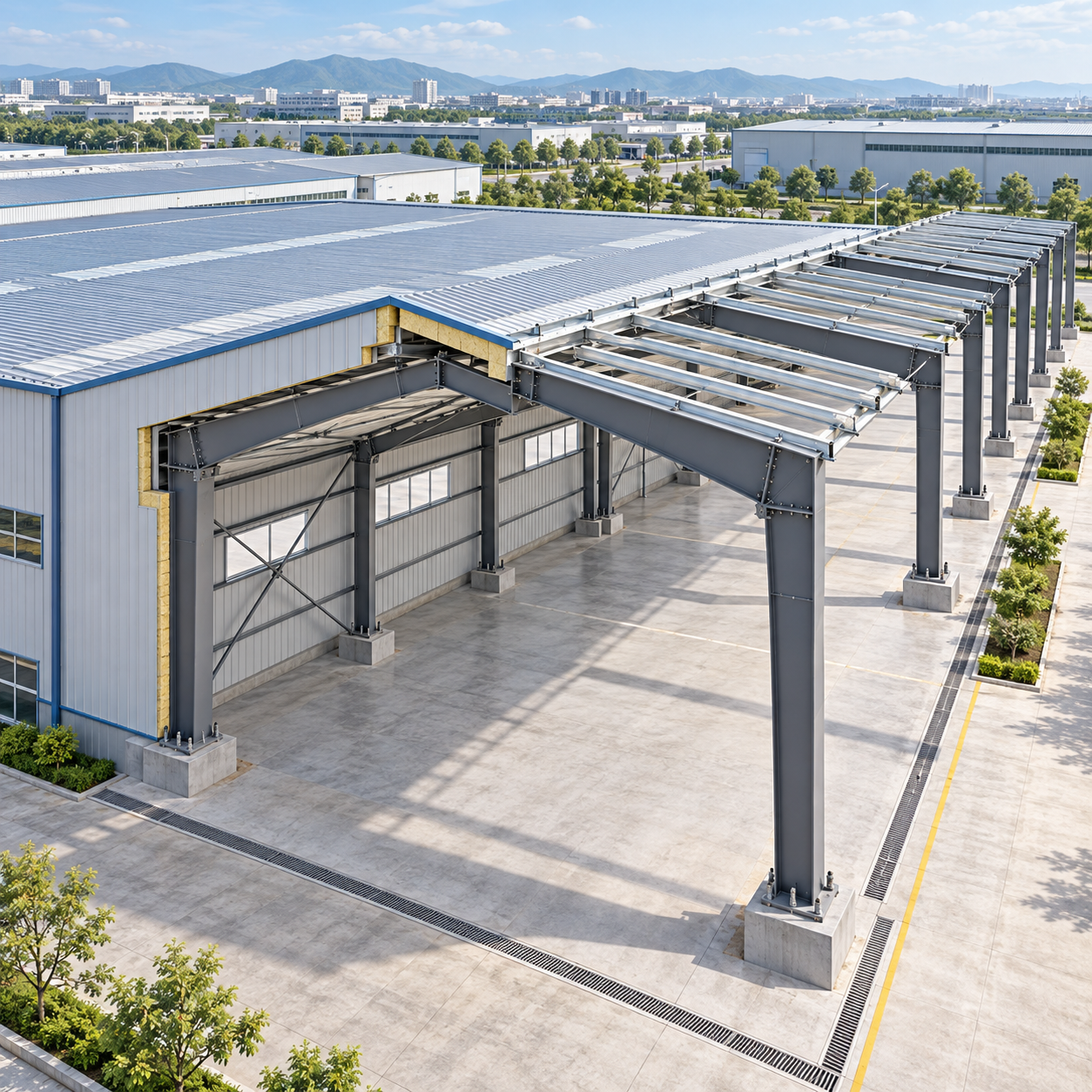
A future end-wall extension is easiest to accommodate when the original building is designed for a defined expansion arrangement. A removable wall helps, but the frame behind it, its foundations, the bracing system, and the roof connections must also support the intended change. Otherwise, adding floor area can require structural reinforcement and disruption inside the existing building.
Good steel building design starts with two layouts: the building you need now and the building you expect after expansion. These do not require identical levels of detail, but they should establish the future footprint, structural grid, operating requirements, and connection strategy before the first steelwork enters fabrication.
Define what the future extension needs to achieve
An end-wall extension normally adds length beyond the building’s gable end while continuing its general roof profile. This can be relatively straightforward when the extension maintains the same width, eave height, and structural arrangement. A wider addition, higher roof, or different operating use introduces other issues and may be better treated as a separate structure.
Start by identifying what the added space will contain. Storage, vehicle maintenance, production equipment, and overhead cranes create different requirements. A future warehouse bay may need uninterrupted forklift access; a manufacturing extension may need crane runway continuity, equipment foundations, or services crossing the original end-wall line.
The expansion brief should establish:
- The end selected for expansion and the land reserved beyond it.
- The likely additional length, bay spacing, and required clear height.
- Whether the completed building needs a clear opening across its full width.
- Future cranes, mezzanines, suspended equipment, solar panels, or other significant loads.
- How construction access will coexist with deliveries, emergency access, and ongoing operations.
A precise expansion date is less useful than a credible future arrangement. Where growth remains uncertain, ask the designer to identify which decisions preserve options and which would commit the project to one configuration.
Choose the right frame at the expansion end
An economical end wall may use intermediate posts supporting an end rafter and wall cladding. Those posts can obstruct the opening when the building is extended. Removing them changes how the remaining structure carries loads, so they cannot simply be taken out because the wall panels are removable.
If the future operation requires an unobstructed connection, a clear-span frame at the expansion line is often the appropriate starting point. It can initially support the end-wall enclosure and later remain as a frame within the enlarged building. However, a clear-span end frame is not automatically designed for its future role.
At the original building end, a frame may support roof loading from one side only. After expansion, it may receive loads from roof bays on both sides. The engineer must assess the actual future tributary area—the roof area whose loads reach that frame—along with connection forces, wind effects, and the final structural arrangement.
The drawings should therefore describe what “expandable end wall” means. Useful requirements include a specified future bay arrangement, permitted loads, removable wall members, and the intended roof connection. A general note saying “allow for future extension” leaves too much open to interpretation.
If the future space can operate through several defined openings, retaining some end-wall posts may be practical. The decision should follow the required movement of goods and equipment, rather than an assumption that every extension needs a completely open interface.
Design foundations and bracing for both building stages
Allowing for a stronger future frame while sizing its foundations only for the initial condition can leave a costly weakness. The expansion-end foundations and anchor rods need to suit the forces associated with the agreed future arrangement. These may include compression, uplift, horizontal reactions, and moments, depending on the structural system.
Foundation planning also needs space. A new footing placed beside an existing one can create excavation difficulties or interact with the existing foundation’s bearing zone. Underground drainage, service trenches, and equipment pits can further restrict the available locations. Establish these relationships before fixing the original foundation layout.
Installing every future foundation immediately is not always justified. Where expansion geometry remains uncertain, unused foundations may become obstacles. A more useful initial investment may be properly designed foundations at the expansion interface, a reserved construction zone, and accessible records of the ground investigation and completed works.
Removing the wall can change how the building resists wind
Bracing carries forces through the building to its foundations. Roof bracing, wall bracing, portal frames, and any engineered contribution from cladding work together as a system. Members in the end wall may form part of that load path even if they appear secondary.
The designer should identify where longitudinal stability comes from before, during, and after extension. If bracing crosses an opening that must eventually be clear, an alternative load path needs to be designed. It may be possible to position permanent bracing away from the expansion interface from the outset.
Temporary conditions also matter. Taking down wall panels can expose the interior to wind and alter internal pressure. Removing posts or bracing before the new structure is stable may leave an incomplete load path. The construction sequence should define temporary bracing and the point at which each existing component can be removed.
Make the enclosure removable without creating a difficult roof junction
A practical removable end wall uses accessible mechanical fixings and details that allow panels, girts, insulation, and flashings to be dismantled in a planned order. Avoid burying necessary connections behind permanent finishes or routing essential services through components scheduled for removal.
Panel reuse can reduce waste, but it should remain conditional. Removal may damage sheets or insulation, and the eventual extension may require different panel lengths or performance. The primary objective is controlled dismantling and reliable weather protection; reuse is an additional opportunity where materials remain suitable.
Roof continuity deserves particular attention. The connection must accommodate the roof system’s support spacing, fastening arrangement, thermal movement, and weathering details. Some roof systems cannot simply receive an extra run of sheets at the existing gable edge without modifying edge components or adjacent panels.
Provide drawings showing how future purlins connect, which edge trims are temporary, and how insulation and air or vapor control layers continue across the junction. In temperature-controlled buildings, a poorly detailed interface can create condensation and air leakage even when the outer roof sheds rain successfully.
Check the final roof geometry as well. Changes in height or shape can introduce snow accumulation conditions where snow loading applies. Roof drainage must be reviewed for the completed arrangement, particularly where the extension affects gutters, outlets, or the discharge route.
Keep the expansion route clear at ground level
A structurally expandable building can still be difficult to extend if its future footprint becomes occupied by permanent site infrastructure. Loading yards, fire access routes, utility equipment, stormwater systems, and underground services can all compete for the same space.
Show the future footprint on the site plan and coordinate it with vehicle movements and drainage. Reserve room for erection equipment and material deliveries as well as the finished building. Construction may need working space beyond the eventual wall line.
Floor continuity requires its own detail. An extension slab does not automatically become structurally continuous with the existing slab. The joint arrangement should suit ground conditions, expected movement, wheel loads, hygiene requirements, and floor finishes. For forklift routes, joint performance and finished floor levels can be more operationally significant than the visibility of the structural connection overhead.
Doors, electrical distribution, compressed air, sprinklers, and drainage should also anticipate the extension where practical. Accessible service routes and planned connection points can reduce shutdown work. Any change to fire compartments, escape routes, or protection systems needs to be assessed for the enlarged building and its intended use.
Decide where spending now will prevent expensive work later
The best initial allowances usually concern components that will be difficult to access or replace once the building is occupied. These often include the expansion-line frame, its foundations, critical connections, and the permanent bracing arrangement.
Other items can wait until the expansion is defined. Manufacturing all future cladding or purchasing unused equipment early can tie up capital while exposing the project to storage damage and changing requirements. The distinction is between preserving structural options and buying a future building before its needs are settled.
Ask suppliers to price the expansion provisions separately from the basic building. This makes the initial cost visible and allows comparison between proposals with equivalent scope. A lower quotation may simply omit the future frame capacity, foundation requirements, or connection engineering included elsewhere.
Put the future arrangement into the supplier’s deliverables
Early coordination with the prefabricated steel building manufacturer helps align frame design, connection detailing, fabrication, and erection. The useful output is a documented expansion strategy that another engineer or contractor can understand when the extension proceeds.
For a factory-direct package supplied internationally, define responsibility for site-specific structural design, foundations, local approval documents, and erection engineering. Manufacturing capacity and certification can support supplier assessment, but neither replaces design for the project’s location, loading conditions, and intended use.
The purchase scope should identify the initial and future configurations, design assumptions, interface reactions, removable components, and connection details. It should also state who will reassess the existing structure when expansion proceeds. Future changes in use, applicable requirements, or building condition can affect whether the original provisions remain suitable.
Keep the approved calculations, fabrication drawings, material records, foundation details, and records of site modifications together. Record concealed connections and underground services before they are covered. These documents give the future design team a reliable starting point and reduce dependence on assumptions about what was built.
Plan the work around a realistic operating sequence
Where access and structural design permit, much of the extension can be erected and enclosed while the original end wall remains in place. Opening the connection later can shorten the period during which the occupied building is exposed. This sequence must be considered during design because the interface may otherwise prevent independent erection or weatherproofing.
A separate structure with a designed movement joint may be more suitable if the addition needs a different height, substantially different loading, or independent movement. It requires careful detailing at floors, roofs, and services, but can avoid forcing incompatible requirements into one continuous frame.
Before releasing the original steelwork for fabrication, request a coordinated review of the completed building layout, the expansion interface, and the proposed construction sequence. The practical test is whether the planned space can be added while preserving the openings, structural capacity, weather protection, and operational access the business will need.
We are more than happy to serve you here. If you have any question, please feel free to contact us.