
Related Posts
- ▶ Prefab vs. Conventional Warehouse Construction: Comparing Timelines
- ▶ Planning a Prefab Warehouse: Clear Span, Height and Loading Bays
- ▶ How Long Does It Take to Build a Commercial Steel Building?
Online Message
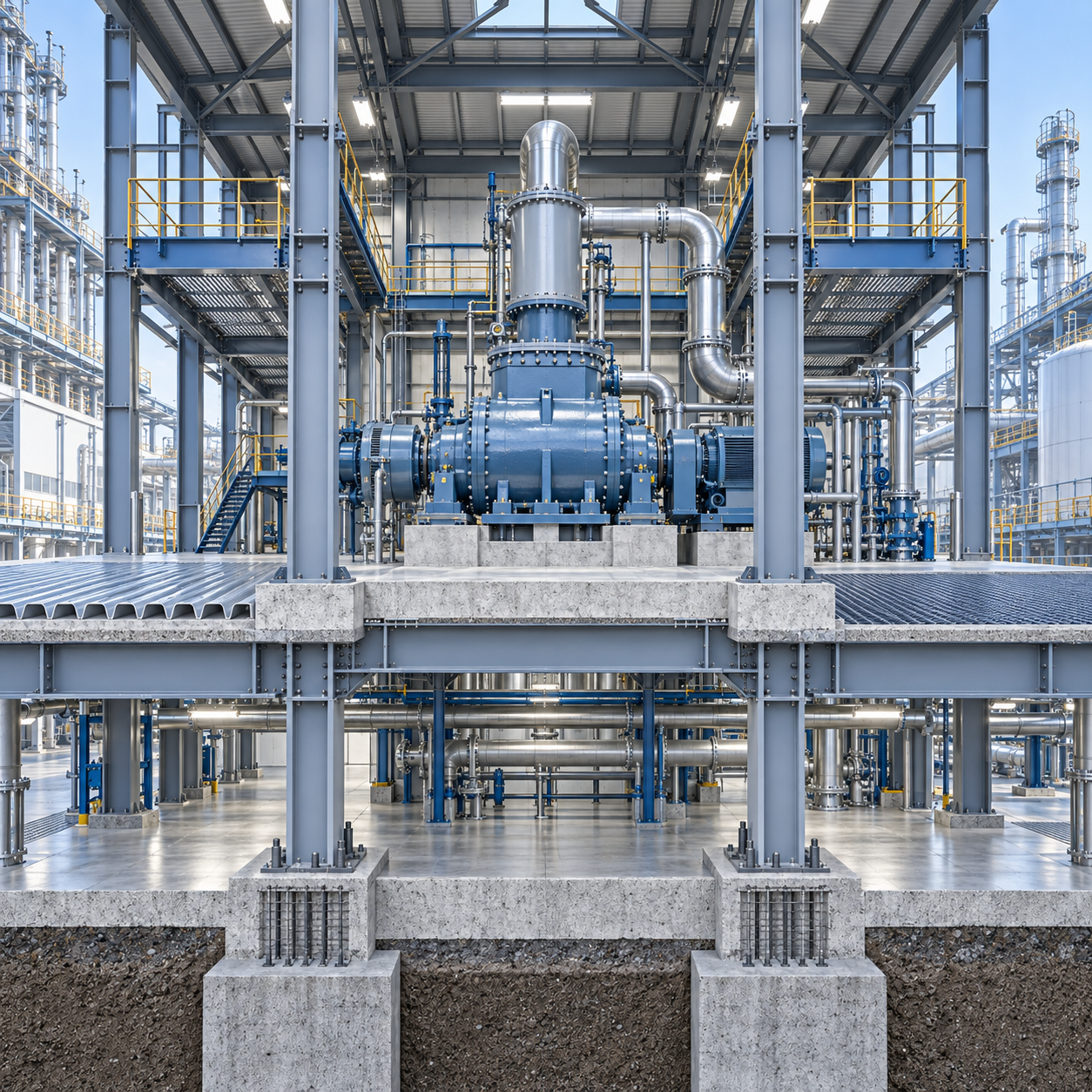
Multi Storey Steel Buildings: Comparing Floor Systems for Heavy Equipment Loads
Multi Storey Steel Buildings designed for heavy equipment need more than strong columns and beams. Their floor systems must manage deflection, vibration, concentrated reactions, durability, and safe long-term operation.
For technical evaluators, the correct choice is rarely based on slab thickness alone. Equipment weight, support geometry, machine dynamics, serviceability limits, and construction sequencing must be assessed together.
This article addresses the practical search intent behind Multi Storey Steel Buildings: determining which floor system can reliably support heavy machinery without creating avoidable structural, operational, or maintenance risk.
Start with the Real Equipment Load Case
The first decision is not whether to specify composite deck, reinforced concrete, or steel grating. It is defining the actual loads transferred from equipment into the floor structure.
Equipment data sheets often state an overall operating weight, but this does not describe the structural demand completely. Evaluators need support-point reactions, footprint dimensions, anchor details, and moving parts.
A machine weighing 80 tonnes may appear manageable when divided across a large floor plate. However, four small baseplates can create extremely high local bearing and punching demands.
Static equipment loads include self-weight, stored materials, piping, fluids, maintenance tools, and temporary installation loads. These must be combined with the relevant live loads required by the governing code.
Dynamic loads require additional attention. Compressors, presses, turbines, pumps, conveyors, test rigs, and reciprocating machinery can introduce cyclic loading, impact, resonance, and fatigue concerns.
For practical design, engineers should request the manufacturer’s dynamic force amplitudes, operating frequencies, start-stop conditions, imbalance forces, and allowable foundation or support movement limits.
The location of equipment is equally important. Loads placed near columns may be transferred efficiently, while loads at midspan can govern beam sizes, slab reinforcement, vibration response, and connection design.
Technical evaluation should also consider future replacement equipment. Designing only for the current machine can create a costly constraint when a tenant upgrades production capacity or changes process technology.
What Performance Criteria Matter Beyond Strength?
Strength verification is essential, but it is only one part of a successful heavy-equipment floor design. Serviceability performance often determines whether the completed building performs as intended.
Deflection can affect machinery alignment, precision manufacturing, drainage falls, partitions, pipe connections, and finishes. A floor that meets ultimate strength requirements may still be unsuitable for sensitive equipment.
Evaluate both total and incremental deflection. Long-term concrete effects, including creep and shrinkage, should be considered where composite or reinforced concrete slabs carry sustained equipment loading.
Vibration criteria should be established early, especially for rotating equipment or processes requiring measurement accuracy. Natural frequency, damping, mode shapes, and peak acceleration can all influence suitability.
Load distribution is another critical factor. Floors must spread concentrated reactions into supporting beams and columns without causing local deck failure, slab cracking, web crippling, or connection overstress.
Fire resistance, acoustic separation, corrosion exposure, access requirements, and repairability should also influence system selection. Heavy equipment floors often operate in environments that differ substantially from ordinary offices.
For Multi Storey Steel Buildings, the governing criteria may vary floor by floor. A production level may need exceptional stiffness, while upper offices or plant rooms can use more conventional composite construction.
The best procurement brief states measurable requirements rather than generic descriptions. Examples include permitted deflection, vibration limits, point-load capacity, equipment foundation details, and required fire rating.
Composite Metal Deck Floors: Efficient but Not Automatically Heavy-Duty
Composite metal deck with concrete topping is widely used in multi-storey steel construction because it offers fast installation, reduced temporary formwork, efficient composite action, and relatively shallow floor zones.
For standard commercial loading, a 130 to 150 mm composite slab can work efficiently with steel secondary beams. This arrangement supports flexible planning and helps coordinate mechanical and electrical services.
However, standard office-grade composite floors should not be assumed suitable for concentrated machinery loads. Heavy equipment may require thicker slabs, closer beam spacing, local reinforcement, or dedicated transfer members.
The profiled deck is primarily a construction-stage form and reinforcement component. Its capacity under concentrated loading depends on deck geometry, slab depth, reinforcement, span direction, and local support conditions.
Composite floors perform well when equipment can be positioned over beams, near columns, or on engineered plinths that distribute loads. They are less economical when large concentrated loads occur repeatedly across open spans.
Local punching shear must be checked around equipment pedestals and heavily loaded baseplates. Additional reinforcing bars, thicker concrete zones, shear studs, or steel distribution plates may be necessary.
Dynamic machines can expose a limitation of lightweight composite floor systems: vibration sensitivity. Increasing slab mass and stiffness may help, but a separate inertia block or independent machine support can be more effective.
Construction speed remains a major advantage. Steel erection, deck placement, shear stud welding, reinforcement installation, and concrete pouring can be sequenced rapidly when the supplier coordinates fabrication and site installation requirements.
For projects combining heavy plant areas with administrative floors, composite construction can remain the preferred baseline. The structural design simply needs targeted strengthening rather than a uniform high-capacity solution everywhere.
A Multi-Storey Office Building solution can use composite deck slabs on efficient 6 x 9 m or 7.5 x 12 m grids, while reserving strengthened zones for heavier service equipment.
Reinforced Concrete Slabs: Mass, Stiffness, and Local Capacity
Reinforced concrete slabs are often selected where heavy loads, robust vibration performance, acoustic separation, fire resistance, and durable industrial finishes are more important than minimum structural weight.
A conventional reinforced concrete slab can distribute concentrated loads effectively, particularly when it is thickened locally or integrated with drop panels, pedestals, reinforced strips, or closely spaced structural beams.
Its mass is useful for equipment that generates vibration. Greater mass can reduce acceleration response, improve damping behavior, and create a more stable platform for machinery requiring accurate alignment.
Concrete floors also provide flexibility for anchor bolts, embedded plates, trenches, housekeeping pads, and equipment grouting. These details are often easier to accommodate than in a thin composite deck assembly.
The tradeoff is increased dead load. Heavier slabs increase demands on beams, columns, foundations, transport planning, erection sequencing, and potentially the entire lateral-force-resisting system.
Wet trades can also affect schedule certainty. Formwork, reinforcement placement, concrete curing, weather protection, and quality control require more site time than a simple deck-and-slab sequence.
For larger spans, reinforced concrete slabs may need deeper beams or post-tensioning to control deflection. The choice should therefore compare total structural depth, not just the apparent simplicity of the slab.
Concrete cracking must be managed through appropriate reinforcement design, jointing, curing, and loading sequence. In industrial environments, uncontrolled cracks can create durability, hygiene, and maintenance concerns.
Where equipment loads are severe but localized, a hybrid approach can be effective. Standard composite floors can serve most areas, while reinforced concrete machine slabs are formed within selected high-load bays.
Heavy-Duty Steel Grating: Best for Access Floors, Not Every Machine
Heavy-duty steel grating systems are valuable in industrial platforms, process mezzanines, maintenance walkways, drainage areas, and elevated access floors where open surfaces provide operational advantages.
Grating allows light, air, water, and spilled materials to pass through the floor. It also simplifies inspection of piping and equipment located beneath elevated process levels.
For concentrated machinery loads, grating is not normally a direct replacement for a concrete slab. Localized wheel loads, machine feet, and vibration can overstress bearing bars or create unacceptable movement.
Heavy-duty welded grating can support substantial distributed loads when designed with appropriate span direction, bearing-bar depth, spacing, support conditions, and fastening details. Its limits must still be documented clearly.
Grating works best where equipment is supported directly by structural steel framing, with the grating serving as an access surface around the machinery rather than its primary load-bearing foundation.
Machine skids can be located over dedicated grillage beams, transfer members, or steel frames. This arrangement directs forces into the main structure while preserving access and drainage around the equipment.
Vibration and noise transmission should be reviewed carefully. Open steel floors may be acceptable for rugged process areas, but they can be unsuitable near laboratories, offices, control rooms, or precision operations.
Maintenance safety also matters. Grating selection should address slip resistance, toe plate requirements, handrail interfaces, opening sizes, corrosion protection, and removable panel arrangements for equipment replacement.
In Multi Storey Steel Buildings, heavy-duty grating is usually a specialized floor solution. It excels in process platforms and service mezzanines, but it should be engineered with dedicated framing for heavy machinery.
How to Match the Floor System to Equipment Type
Static storage tanks, electrical transformers, and packaged utility skids may be suitable for reinforced composite slabs when load reactions are distributed and the supporting beam layout is coordinated properly.
Heavy presses, forging equipment, impact machinery, and reciprocating compressors often need a more substantial concrete base or an independent foundation system to control dynamic forces and fatigue effects.
Conveyors create moving loads that can travel across multiple bays. Their support legs should be mapped precisely so secondary beams, primary beams, bracing, and connections are designed for actual reactions.
Data center equipment, battery systems, laboratory instruments, and medical devices may have moderate weight but demanding deflection or vibration limits. Serviceability can therefore govern the structural design.
Roof-mounted plant is another common challenge. Cooling towers, air-handling units, chillers, and rooftop generators may require strengthened roof beams, vibration isolation, and load paths that avoid overloading interior members.
Where equipment contains liquids, accidental leakage and maintenance activities must be included in planning. Curbs, drainage, protective coatings, and localized corrosion-resistant details may influence the preferred floor construction.
Technical evaluators should avoid accepting broad statements such as “industrial load capable.” A credible proposal identifies the equipment schedule, each reaction point, relevant load combinations, and design assumptions.
Coordinate the Steel Frame, Services, and Floor Early
Floor selection cannot be separated from the steel frame. Beam depths, column spacing, slab thickness, bracing locations, penetrations, and service routes all influence capacity, cost, and buildability.
Long-span secondary beams can create open floor plates, but they may increase vibration sensitivity under machinery. Shorter spans can improve stiffness while adding columns that affect process layout and access.
Cellular or fabricated beams with web openings can route services through the structural zone. This helps preserve floor-to-floor height, but opening locations require careful checks near heavy equipment reactions.
A coordinated BIM model is especially valuable when machinery, cable trays, ducts, piping, fire protection, and access platforms compete for the same structural space. Late coordination changes are expensive.
For office floors above retail, parking, or industrial podiums, transfer conditions deserve special attention. Heavy loads from upper plant areas may require transfer girders that affect the lower-level column layout.
Steel grades such as Q355B, S355JR, and ASTM A572 Grade 50 can be selected according to applicable codes, availability, connection requirements, and project-specific certification requirements.
Fabrication quality supports reliable field performance. Material traceability, controlled welding, ultrasonic testing where specified, accurate drilling, and documented inspection reduce uncertainty before erection begins.
Use Codes, Testing, and Documentation as Decision Controls
Code compliance should be established at the beginning of technical evaluation. Applicable requirements may include local building regulations, loading standards, steel design codes, concrete design codes, fire provisions, and seismic rules.
International projects may require designs aligned with AS-NZS, ASTM-based specifications, European material standards, or locally adopted structural codes. The governing hierarchy should be stated in the contract documents.
Equipment supplier information should be treated as a formal design input. It must be reviewed, clarified, and incorporated into calculations rather than copied into drawings without structural verification.
For unusual dynamic machinery, specialist vibration analysis may be justified. Finite-element models, modal analysis, fatigue checks, and manufacturer acceptance criteria can prevent costly modifications after commissioning.
Documentation should include design calculations, floor loading plans, beam reaction schedules, connection details, material certificates, welding records, coating specifications, and installation guidance appropriate to the project scope.
Manufacturers with ISO-controlled production systems can support consistency in procurement. Third-party inspection before shipment may also be useful where the project team requires independent verification of fabrication quality.
Technical teams should distinguish between certified materials and certified structural performance. Mill certificates confirm material properties, while project engineering confirms that the complete floor and frame system meets intended loads.
Conclusion: Select the System Around the Risk, Not the Label
There is no universal best floor system for Multi Storey Steel Buildings carrying heavy equipment. Composite decks, reinforced concrete slabs, and steel grating each solve different structural and operational problems.
Composite floors are efficient for broadly distributed loads and adaptable commercial-industrial spaces. Reinforced concrete is often stronger for severe point loads, stiffness, and vibration control. Grating is effective for access-oriented process platforms.
The soundest decision begins with verified equipment reactions and operating conditions. It then checks deflection, vibration, local capacity, load paths, fire performance, construction sequence, maintenance access, and future adaptability.
For technical evaluators, the key is to demand a project-specific structural response. A floor system should be designed around actual machinery and operational risk, not selected from a generic building specification.
We are more than happy to serve you here. If you have any question, please feel free to contact us.