
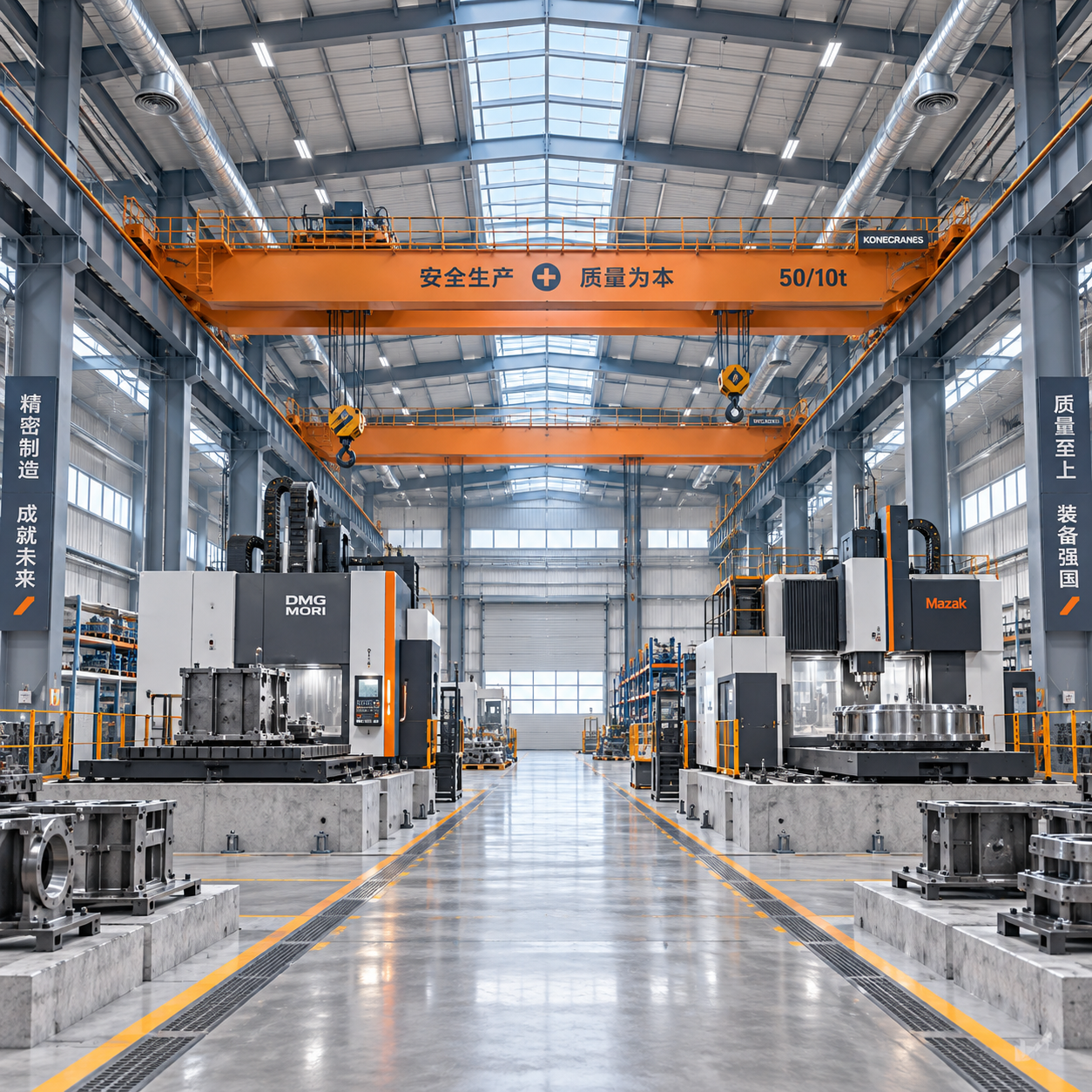
How to Specify a Steel Industrial Workshop for Heavy Manufacturing Equipment
Specifying a Steel Industrial Workshop for heavy manufacturing equipment requires more than selecting a building size. Technical evaluators must assess crane loads, equipment foundations, clear spans, roof loading, corrosion protection, code compliance, and future expansion requirements.
This guide outlines the engineering and procurement factors that define a reliable steel workshop, supporting safe operations, efficient equipment installation, and durable long-term manufacturing capacity.
Start With the Manufacturing Process, Not the Building Footprint
The core search intent behind a Steel Industrial Workshop specification is practical risk reduction. Evaluators need a building that accommodates real production loads, installation methods, maintenance access, and planned output growth.
Begin by mapping the manufacturing process from material receipt through fabrication, assembly, testing, storage, and dispatch. This determines where structural capacity, height, access, ventilation, and crane coverage are actually required.
A preliminary layout should identify each major machine, equipment weight, operating envelope, maintenance clearance, utility connection, and material-handling route. Without this information, structural sizing becomes an assumption rather than an engineered decision.
Do not treat equipment positions as fixed drawings only. Large presses, machining centers, furnaces, conveyors, and automated lines often require future replacement routes that affect bay spacing, wall openings, and roof removal zones.
Technical evaluators should request a coordinated process layout before approving column grids. A clear-span area may benefit operations, but its cost must be evaluated against crane demand, roof loading, and expansion requirements.
Production flow also determines internal traffic conflicts. Forklifts, trailers, maintenance vehicles, overhead cranes, and personnel routes must coexist safely without forcing later alterations to columns, bracing, doors, or foundations.
Define Crane Loads Before Selecting the Primary Steel Frame
For heavy manufacturing facilities, the overhead crane system commonly governs the Steel Industrial Workshop design. Crane capacity alone is insufficient because wheel loads, impact factors, surge forces, and duty classification all matter.
Specify the maximum lifted load, crane self-weight, hook approach, span, runway length, lifting frequency, travel speed, and operating class. A 20-ton crane used occasionally creates a different design condition than continuous production lifting.
Crane suppliers should provide certified maximum wheel reactions, horizontal longitudinal forces, transverse surge loads, buffer forces, and load combinations. The building engineer should use these data rather than generic crane tables.
Runway beams, crane brackets, column sections, roof bracing, and foundation anchors must work as one load path. An underspecified bracket connection can produce excessive deflection even when the main columns appear adequate.
Check allowable runway deflection and rail alignment limits early. Excessive movement affects crane travel, increases wheel wear, and can create repeated maintenance problems that are expensive after commissioning.
Where two cranes operate on the same runway, define whether simultaneous lifting is expected. Also clarify tandem lifting, maintenance isolation, future crane upgrades, and whether runway beams must accept larger wheel spacing later.
For high-duty installations, consider fatigue design at crane connections and brackets. Repeated load cycles can control the connection detail even where ultimate strength calculations show sufficient nominal capacity.
Set Column Spacing, Clear Height, and Span Around Equipment Reality
Clear height should be measured below the lowest obstruction, including crane hooks, runway beams, bracing, lighting, ducts, and fire services. Eave height alone does not confirm usable installation height.
Define the highest equipment component that must enter, be assembled, or receive maintenance. Add lifting clearance, rigging depth, safety margin, and any required crane hook approach distance.
Column spacing should support the equipment layout while controlling structural cost. Wider bays may reduce internal obstructions, but they often increase member sizes, crane beam demands, and erection complexity.
For production lines requiring uninterrupted movement, clear spans can be justified. However, technical evaluators should compare a clear-span solution against a multi-bay layout with carefully located columns and lower steel tonnage.
Roof slope and framing depth influence usable height near exterior walls. This is important for tall machinery, vertical storage racks, exhaust stacks, and equipment requiring service platforms.
Door locations also need structural coordination. Large roller shutters, sliding doors, and equipment access openings interrupt wall bracing and may require portal frames, moment connections, or transfer members.
Separate Building Foundations From Equipment Foundations
A heavy equipment workshop requires two related but distinct foundation systems. Building columns transfer structural loads to footings, while machinery foundations must manage vibration, dynamic forces, settlement, and operational alignment.
Do not assume a standard slab-on-grade can support heavy machinery. Presses, forging equipment, compressors, machine tools, and rotating systems may require isolated reinforced concrete blocks or piled foundations.
The geotechnical report should establish bearing capacity, groundwater conditions, settlement potential, soil aggressiveness, seismic classification, and recommendations for both building foundations and machine bases.
Equipment suppliers should provide static loads, dynamic loads, anchor bolt forces, allowable vibration, baseplate dimensions, and grouting requirements. These values should be incorporated before fabrication drawings are released.
Where vibration-sensitive equipment operates near offices, laboratories, or precision machines, structural isolation may be necessary. Isolation joints, separate slabs, and vibration-control details should be developed during detailed engineering.
Coordinate underground services before foundation construction. Drainage pits, cable trenches, compressed-air lines, hydraulic piping, and process utilities can conflict with footing locations or reduce slab performance.
Foundation tolerances deserve explicit specification. Column base plates, anchor rod patterns, crane rail elevations, and equipment bolt groups require survey control that ordinary warehouse construction may not provide.
Specify Roof, Wall, and Environmental Loads for the Actual Site
A Steel Industrial Workshop must be designed for its project location, not a generic export configuration. Wind, snow, rain, seismic demand, temperature range, and local code combinations affect the steel frame.
Provide the exact site location, elevation, terrain category, exposure condition, and nearby topography. Coastal zones, open industrial estates, mountainous sites, and cyclone regions may require substantially different structural solutions.
Roof loading should include maintenance access, suspended utilities, dust collection ducts, fire-protection piping, solar systems, lighting, cable trays, and future process equipment. These items are often omitted from early requests.
Ask whether rooftop photovoltaic panels will be installed immediately or later. Future solar loading may require larger purlins, stronger roof bracing, connection reinforcement, and a verified waterproofing arrangement.
Internal pressure conditions matter where large doors remain open during operations. Wind loading on cladding, roof panels, and wall bracing can change significantly when the building envelope is partially open.
For hot processes, consider thermal effects from furnaces, welding zones, or heat-treatment equipment. Insulation, roof ventilation, smoke exhaust, and localized heat shielding may be required to protect occupants and steel components.
Choose Steel Grades and Connections That Match the Design Standard
Material selection should be linked to the governing design code, member thickness, welding method, temperature conditions, and availability. Common structural grades include Q355B, Q235B, S355JR, and S275JR.
The purchase specification should state the required standard and avoid mixing material designations without confirmation. Equivalent nominal strength does not automatically confirm equivalent chemistry, toughness, certification, or fabrication suitability.
Require mill certificates and traceability for primary structural members, crane-supporting members, and critical connection plates. Traceability should remain available from material receipt through cutting, welding, inspection, and packing.
Connection design is as important as member sizing. Bolted site connections simplify erection, while shop-welded assemblies can improve quality control and reduce work performed at height.
For moment frames, crane brackets, and heavily loaded splices, specify bolt grade, slip-critical requirements where applicable, weld categories, nondestructive testing scope, and inspection acceptance criteria.
Fabrication capability should include controlled welding procedures, qualified welders, dimensional checks, and documented inspection records. For critical welds, ultrasonic testing and third-party inspection should be available before shipment.
Plan Corrosion Protection for Operating Conditions, Not Appearance
Coating selection should be based on corrosion category, humidity, chemical exposure, cleaning procedures, coastal conditions, and maintenance access. Paint color alone says little about long-term steel protection.
For normal dry industrial interiors, a properly specified painted system may perform well. For humid, chemical, marine, or washdown environments, hot-dip galvanizing or duplex protection may offer better lifecycle value.
Specify surface preparation, such as blast cleaning to Sa2.5 where required, primer chemistry, dry-film thickness, topcoat system, and inspection methods. Coating thickness should be measured and recorded before packing.
Pay attention to concealed areas, base connections, roof drainage details, gutters, wall interfaces, and areas beneath crane runways. Water retention and inaccessible surfaces create corrosion risks that repainting cannot easily solve.
Projects involving humid agricultural processing illustrate the importance of exposure classification. A Steel Structure Dairy Farm Building may use galvanizing and duplex coatings because ammonia-rich moisture rapidly degrades inadequately protected steel.
Although heavy manufacturing conditions differ from livestock facilities, the same principle applies: specify protection around the actual airborne contaminants, moisture cycles, and cleaning regime rather than selecting a standard finish.
Coordinate Cladding, Ventilation, and Building Services Early
Wall and roof cladding must support operational requirements, including thermal control, daylight, fire performance, condensation management, acoustic conditions, and future penetrations for utilities or exhaust systems.
Specify insulation thickness according to climate and process heat. In metal buildings, uncontrolled condensation can damage stored materials, affect electrical systems, and create unsafe wet floors near production areas.
Natural ventilation may be adequate for some fabrication operations, but welding fumes, dust, heat, and chemical vapors often require engineered extraction. Structural framing must allow for ducts, fans, and suspended filtration equipment.
Coordinate fire protection with roof framing and clear heights. Sprinkler pipe supports, smoke vents, fire shutters, and emergency lighting add both load and routing constraints that should appear in coordinated drawings.
Daylighting panels can reduce electrical demand, but their placement should avoid glare above inspection stations, machine controls, and welding areas. They must also meet roof load, weathering, and fire requirements.
Drainage should receive the same attention as the main frame. Roof slopes, gutters, downpipes, overflow provisions, and site discharge capacity must suit the local rainfall intensity and maintenance conditions.
Build Future Expansion Into the Initial Steel Workshop Design
Future expansion is often cheaper when defined before the first workshop is fabricated. Evaluators should identify whether growth will occur longitudinally, laterally, vertically, or through additional crane capacity.
An expandable end wall may use bolted framing, removable cladding, planned bracing relocation, and foundations arranged for the next bay. These provisions avoid costly demolition when production capacity increases.
Where future crane upgrades are likely, columns and foundations may need reserve capacity. Retrofitting crane brackets and runway beams after operations begin can disrupt production and require extensive temporary works.
Reserve space for electrical rooms, compressors, water treatment, dust collection, spare-part storage, and maintenance workshops. These support functions often expand alongside manufacturing equipment and can constrain later layouts.
BIM-based coordination can help visualize expansion interfaces, equipment zones, service routes, and erection sequencing. It is especially useful where the workshop combines heavy equipment, multiple cranes, and complex process utilities.
Use a Procurement Package That Produces Comparable Quotations
Technical evaluators should issue a structured request for quotation rather than asking suppliers for a price per square meter. Area-based pricing hides differences in steel weight, design loads, coating, and connection scope.
The enquiry package should include site information, applicable code, dimensions, column grid, eave height, crane data, equipment layout, loading criteria, geotechnical information, cladding requirements, and intended expansion strategy.
Also define whether the supplier provides engineering calculations, fabrication drawings, anchor plans, packing lists, erection manuals, installation supervision, and localized documentation required by the destination country.
Ask suppliers to state design assumptions clearly. A transparent quotation identifies steel grades, member weights, connection type, cladding thickness, coating system, excluded works, delivery terms, and inspection scope.
Factory capability should be evaluated beyond stated annual output. Review quality procedures, welding equipment, CNC cutting accuracy, shop detailing capacity, material traceability, export packing, and previous projects with similar crane demands.
A manufacturer with ISO-controlled processes, certified steel supply, documented weld inspection, and established export experience can reduce coordination risk, particularly where fabrication and site erection occur in different countries.
Verify the Design Before Fabrication and Before Site Erection
Before production begins, review general arrangement drawings, design calculations, connection details, crane runway elevations, foundation reactions, material schedules, and cladding layouts against the approved process equipment plan.
Confirm that all dimensions are coordinated with equipment vendor drawings. The most damaging late changes usually involve crane heights, machine access, maintenance platforms, duct penetrations, and major door openings.
During fabrication, inspection should cover material identification, weld quality, member dimensions, hole locations, trial assembly where needed, coating thickness, marking, and packing protection for sea transport.
At site, erection quality depends on foundation accuracy, bolt tightening, crane rail alignment, bracing installation, weatherproofing, and controlled sequencing. A correct factory design can still fail operationally through poor installation control.
Require punch-list closure before commissioning. Verify door operation, roof drainage, cladding fasteners, coating damage repairs, crane travel, electrical grounding interfaces, and access provisions for routine maintenance.
Conclusion
A successful Steel Industrial Workshop specification begins with the manufacturing process and converts operating requirements into measurable structural, foundation, crane, envelope, and quality-control criteria.
For technical evaluators, the priority is not selecting the lowest initial steel price. It is confirming that the workshop safely carries real loads, supports installation, controls lifecycle risk, and accommodates future manufacturing demands.
Use coordinated equipment data, site-specific design criteria, transparent supplier assumptions, and documented inspection requirements. This approach creates a workshop that performs as a production asset rather than simply functioning as a building.