
Related Posts
- ▶ Can a Steel Industrial Workshop Be Built Near Residential Areas?
- ▶ Natural or Mechanical Ventilation for Steel Industrial Workshops?
- ▶ Which Insulation Is Best for a Steel Industrial Workshop?
Online Message
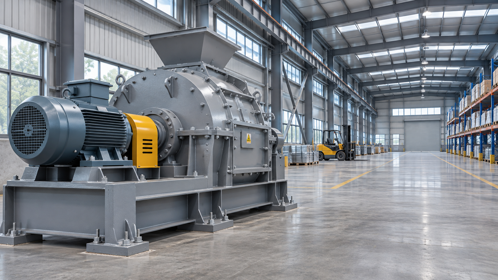
Determining steel industrial workshop floor load capacity requires more than selecting a standard design load. Engineers must account for equipment weights, forklift traffic, storage configurations, point loads and ground conditions, as well as the applicable building codes.
This guide explains the key factors that influence slab design and load ratings, helping technical evaluators identify project requirements, compare design options and coordinate with steel building suppliers and structural engineers.
How Much Floor Load Capacity Does an Industrial Workshop Need?
There is no single floor load capacity suitable for every steel industrial workshop. The required performance depends on the heaviest credible combination of equipment, traffic, storage and ground conditions.
For early planning, a distributed load of 5 to 10 kN/m² may be considered for some light industrial areas, but it is only a preliminary discussion range.
Heavier manufacturing, concentrated storage or frequent forklift movements can require substantially different provisions. Local code requirements and the actual operating loads must determine the design.
Most importantly, a floor specified at a given load per square meter is not automatically suitable for a machine foot, rack post or forklift wheel applying a concentrated force.
A useful assessment therefore identifies both the overall loading and the individual contact loads, then checks the slab, supporting ground and foundations for each relevant condition.
Which Loads Should Technical Evaluators Identify First?
Begin with a scaled workshop layout showing equipment, storage, vehicle routes and future expansion areas. Assign realistic loads to each zone instead of applying one assumed value everywhere.
For every load, document its magnitude, contact area, location, frequency and expected duration. Where several loads can occur together, identify the governing combinations for the engineer.
Fixed Equipment and Machinery
Collect the operating weight of each machine, including tooling, workpieces, fluids and accessories. Shipping weight alone can underestimate the load imposed during normal production.
Request a base drawing showing support points, dimensions and individual reactions. Uneven weight distribution can make one machine foot considerably more demanding than the average suggests.
Dynamic machines, such as presses and rotating equipment, may also require vibration limits, fatigue checks or an independent foundation. Ask the manufacturer for operating forces and frequencies.
Include installation and maintenance conditions, such as a machine being moved on skates or lifted by temporary equipment. These stages can govern local floor requirements.
Forklifts and Other Moving Loads
Use the vehicle manufacturer’s maximum loaded axle and wheel loads, including the carried payload and attachments. Rated lifting capacity by itself does not describe the load on the slab.
Record tire type, wheel spacing, contact dimensions and travel routes. Hard tires, small contact areas, repeated turning and travel across joints can increase local pavement demands.
Check loading during lifting and braking where relevant, using appropriate design guidance. The floor design should also consider traffic frequency and the consequences of joint deterioration.
Racking, Stock and Stored Materials
For pallet racking, obtain the maximum load per rack post, including stored goods and the rack itself. Check post locations, baseplate dimensions and anchor requirements.
Storage layouts should identify stack height, material density, pallet weights and aisle widths. Concentrated stockpiles or coil storage may require local strengthening or dedicated foundations.
Check whether storage loads are sustained for long periods and whether adjacent racks or machines act simultaneously. These details affect settlement and local load interaction.
Why a Load per Square Meter Is Not Enough
A uniformly distributed load describes force spread over an area, typically in kN/m². It is useful for planning, but it does not define every failure mechanism.
A point load describes force concentrated at a small contact area, such as a rack baseplate or machine foot. Wheel loads are moving concentrated loads with additional joint considerations.
For example, a 40 kN machine supported equally on four feet imposes 10 kN per foot. That simplified figure still needs checking against actual manufacturer reactions.
If each foot has a 200 mm by 200 mm baseplate, its average contact pressure is 250 kN/m² before considering uneven contact or other effects.
That pressure must not be compared directly with a workshop’s 5 kN/m² distributed load rating. The slab spreads load into the ground, and each load case needs its own analysis.
The structural engineer evaluates bending, punching or local bearing as applicable, together with subgrade response and serviceability. A single pressure calculation cannot establish slab adequacy.
What Determines the Required Slab Design?
Ground Conditions and Subbase
The slab relies on the ground beneath it. Variable fill, weak soil, poor compaction or moisture changes can cause differential settlement and cracking even when concrete strength is adequate.
A geotechnical investigation should establish suitable design parameters, groundwater conditions and preparation requirements. The engineer can then assess whether soil improvement or a different foundation approach is needed.
The subbase also needs appropriate material, thickness, drainage and compaction. Its purpose is to provide consistent support and a workable construction platform for the slab.
Do not substitute soil bearing capacity directly for a modulus of subgrade reaction. They describe different properties, and their use depends on the selected design method.
Slab Thickness, Concrete and Reinforcement
Slab thickness influences bending resistance and stiffness, but an apparently substantial slab can still fail under concentrated loads or poor ground support. Thickness must follow the design checks.
Concrete strength, shrinkage characteristics, curing and construction tolerances also matter. Reinforcement may control cracking or contribute to structural resistance, depending on its type, position and design.
Steel fibers, welded wire reinforcement and conventional reinforcing bars are not interchangeable by default. Their suitability depends on the design method, load cases and performance requirements.
For heavy machines, the solution may include a thickened slab, isolated foundation or engineered connection to other foundations. The choice depends on loads, vibration and ground conditions.
Joints and Floor Flatness
Joints are common locations for damage under wheeled traffic. Their spacing, load transfer, edge protection and alignment with vehicle routes deserve attention during design and construction.
Define floor flatness and levelness according to the equipment and storage system. High racking, automated vehicles and precision machinery may have tighter tolerances than general workshop operations.
Specify how tolerances will be measured and when acceptance occurs. Construction sequencing, shrinkage and later settlement can affect the floor’s performance after the initial survey.
How Do You Establish a Preliminary Floor Load Specification?
Start with the intended use of each workshop zone and identify the applicable local building regulations. Confirm whether a governing authority or insurer imposes additional requirements.
Then prepare a load schedule that distinguishes distributed storage loads, machine reactions, rack post loads and vehicle wheel loads. Include units and the source of each value.
Add drawings that show contact footprints, wheel paths, joint locations and distances from slab edges. Loads near edges, openings or adjacent foundations may require separate checks.
Identify simultaneous operating scenarios, including the heaviest credible equipment and storage arrangement. Avoid simply adding unrelated maximum loads if they cannot occur together; document that assumption.
Share geotechnical findings and required floor tolerances with the structural engineer. Where information is unavailable, record provisional assumptions and assign responsibility for confirming them before final design.
Finally, request a design deliverable that states permitted loads, locations and conditions. A useful rating should explain its limits and identify loads requiring additional engineering review.
What Should You Ask a Steel Building Supplier?
Confirm whether the supplier’s quotation includes the ground investigation, slab design, foundations and construction, or only the steel frame and building envelope. Responsibilities vary between projects.
Ask how column reactions, anchor bolts and bracing loads will be transferred to the foundations. These loads are distinct from equipment and storage loads applied to the floor.
Request the applicable design codes, load assumptions, material specifications and calculation responsibilities. For an international project, establish which local engineer will review and approve the design.
Where a supplier offers an integrated package, check whether equipment foundations, joints, floor finishes and installation tolerances are included. Clarify who coordinates changes after equipment selection.
Factory production capacity and certification credentials can support supplier evaluation, but they do not establish a particular slab’s load capacity. Project calculations and local compliance remain essential.
How Can You Compare Floor Design Options?
Compare alternatives against the same documented load cases and performance criteria. A lower initial slab cost may be less attractive if it restricts equipment placement or forklift routes.
Consider whole-life costs, including ground improvement, joint maintenance, downtime, future modifications and potential production disruption. Ask designers to explain the assumptions behind each option.
A uniform heavy-duty slab can provide layout flexibility, while reinforced zones or separate equipment foundations may reduce construction costs where heavy loads are concentrated and locations are stable.
Future capacity should be specified deliberately. If heavier machinery or taller storage is likely, provide credible future loads and locations so the engineer can evaluate the investment.
Before accepting a proposed upgrade, check whether it also requires stronger foundations, improved subgrade or different joints. Increasing slab thickness alone may not address the governing constraint.
Common Mistakes That Can Undermine a Workshop Floor
A frequent mistake is using a generic floor rating from another project without checking its soil conditions, load footprints or traffic patterns. Similar buildings can have different requirements.
Another is designing around equipment catalogs before final machines are selected. Changes in support spacing, wheel configuration or storage height can invalidate earlier assumptions.
Uncoordinated responsibilities create risk as well. The frame supplier, equipment vendor, geotechnical consultant and floor designer should exchange information before drawings and construction details are finalized.
After construction, uncontrolled operational changes can exceed the approved design. Maintain a floor load plan and review proposed equipment moves, new racks and heavier vehicles before implementation.
Making the Final Capacity Decision
The right steel industrial workshop floor load capacity is the one supported by documented operating loads, suitable ground conditions and an engineered design for the relevant locations.
Use preliminary load ranges only to start discussions. For procurement and construction, require verified equipment reactions, vehicle data, storage loads, geotechnical information and applicable code checks.
A clear load schedule and defined supplier responsibilities give technical evaluators a stronger basis for comparing proposals, controlling construction risk and planning future workshop use.
We are more than happy to serve you here. If you have any question, please feel free to contact us.