
Related Posts
- ▶ Prefab vs. Conventional Warehouse Construction: Comparing Timelines
- ▶ Planning a Prefab Warehouse: Clear Span, Height and Loading Bays
- ▶ How Long Does It Take to Build a Commercial Steel Building?
Online Message
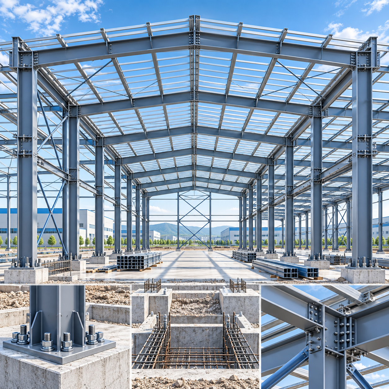
Column Spacing Rules That Improve Material Efficiency in Multi Span Steel Buildings
In a Multi Span Steel Building, column spacing is not a drafting detail to be settled after the main frame has been selected. It is one of the decisions that determines the building’s steel weight, foundation demand, roof drainage arrangement, bracing layout, usable floor area, and capacity to accommodate operations over time. A grid that appears economical because it reduces the number of columns can produce heavier rafters, deeper beams, larger connections, and more demanding erection requirements. A grid that is too tight can do the opposite: it may reduce member sizes while adding foundations, base plates, transport pieces, and obstacles to internal circulation.
The practical objective is not to maximize span or minimize the number of columns. It is to establish a regular structural grid that follows the building’s loads and operating constraints, then test whether departures from that grid create enough functional benefit to justify their structural cost. This is especially important for multi-span industrial buildings, where internal columns share roof load, restrain transverse frames, and often affect the entire load path rather than one isolated bay.
Start with the grid, not with a preferred member size
Column spacing has two directions. Transverse spacing defines the width of each span across the building; longitudinal spacing defines the distance between portal frames along its length. They must be evaluated together. A 20 m span may be efficient with one longitudinal bay length under a light roof, yet need a different bay length where crane loads, solar panels, suspended services, or high wind suction govern the design.
For technical evaluation, the first drawing should identify process lanes, vehicle paths, storage modules, machinery footprints, fire separations, maintenance access, drainage falls, and planned expansion zones. Those constraints should establish a candidate grid. Only then should the structural engineer compare frame alternatives. Starting with a nominal “standard” span and forcing the operation to fit it usually transfers cost elsewhere: rack layouts become compromised, equipment needs awkward offsets, or later service penetrations cut through members that were not designed for them.
Regularity matters because it simplifies far more than fabrication. Repeated bays permit repeated purlin lines, bracing locations, connection details, wall-panel modules, and foundations. They also reduce the chance that a site team will place components incorrectly. A building does not need to be perfectly uniform, but exceptions should be deliberate and concentrated where the operational return is clear, such as a loading door zone, a crane bay, or a future extension interface.
The material trade-off behind wider and tighter bays
Wider transverse spans usually provide cleaner internal space. This can be valuable for forklifts, conveyors, production lines, and large storage areas. The trade-off is increased bending moment and deflection in rafters and roof beams. As spans rise, members may need more depth, thicker plates, additional haunch reinforcement, or a changed structural system. The savings from eliminating a line of columns should therefore be compared with the added steel across every affected frame, not just with the removed columns.
Closer spans reduce rafter demand because internal columns provide intermediate support. Yet each new column line introduces foundations, anchor assemblies, base connections, wall interfaces, and potential clashes with doors or operations. In poor soil conditions, foundation costs can materially alter the result. A closely spaced grid that appears light in a steel take-off may be less attractive after geotechnical requirements and concrete quantities are included.
Longitudinal bay spacing creates a similar trade-off. Longer bays reduce the number of primary frames and foundations, but increase purlin span, roof sheeting support demands, and the force transferred by longitudinal bracing. Shorter bays add frames while allowing lighter secondary members. The optimum is often governed by the roof system and service loads rather than by the portal frame alone. This is why a comparison should include primary steel, secondary steel, bracing, connections, cladding support, foundations, and erection sequence.
Do not confuse minimum tonnage with minimum project cost
A lower steel weight is useful, but it is not a complete measure of efficiency. Very slender members may be economical in weight while requiring more demanding transport control, temporary erection restraint, or site welding. Conversely, a slightly heavier repeated frame can reduce fabrication complexity and shorten assembly time. Material efficiency should mean that each component is doing useful work within a constructible, inspectable, and maintainable system—not merely that the bill of materials is shorter.
For factory-supplied structures, shipping limits deserve early attention. A frame arrangement that creates long welded assemblies may require field splices or different packaging even if it performs well structurally. The splice locations should be designed around realistic erection access and connection tolerances, rather than being left as a workshop convenience.
Loads that should change the spacing decision
Dead load is only the starting point. Roof sheets, insulation, purlins, gutters, suspended lighting, sprinkler mains, cable trays, HVAC units, photovoltaic systems, and maintenance loads can all influence the required grid. Where equipment is likely to be added after commissioning, the design team should distinguish between confirmed loads and reserved capacity. Assuming future loads without defining them can lead either to unnecessary steel or to an underprepared roof.
Environmental actions require the same discipline. Wind pressure and suction vary by site, building height, roof geometry, openings, terrain, and the applicable code. Snow load may govern roof members in some locations, while rainfall intensity and roof drainage can control ponding checks and gutter design elsewhere. Seismic design can change the preferred bracing arrangement, connection detailing, and column-base behavior. There is no universal bay spacing that can be described as compliant without confirming the governing local standard and site parameters.
Cranes deserve a separate structural conversation. A crane runway introduces vertical wheel loads, lateral surge forces, longitudinal braking effects, fatigue considerations, and strict alignment expectations. The column grid should support the crane geometry rather than treating the crane as an attachment to a standard warehouse frame. In many cases, a dedicated crane line or locally strengthened bay is more rational than making the entire Multi Span Steel Building heavier.
- Confirm whether roof-mounted equipment loads are point loads, line loads, or distributed loads.
- Separate operational live loads from occasional maintenance access.
- Identify locations where wall openings interrupt normal bracing or girt patterns.
- Check whether internal columns can carry future mezzanines, process platforms, or conveyor supports.
- Review serviceability limits alongside strength checks; excessive deflection can damage cladding, drainage, machinery alignment, and finishes even where members remain safe.
Use localized strengthening instead of overdesigning the whole frame
One of the most reliable ways to control steel use is to avoid applying exceptional loads to every bay. A heavy suspended unit, an equipment platform, a large louver opening, or a crane access zone may require local reinforcement, transfer members, or a revised bracing panel. That is often preferable to increasing the size of all rafters and columns across the building.
This principle becomes more significant in multi-level processing facilities. Consider a grain-processing frame with three to six process levels. Typical planning grids such as 8 × 10 m or 9 × 12 m may be workable reference points, but their suitability depends on machinery loads, openings, vertical conveyors, and vibration-sensitive zones. Floor live loads of 8–15 kN/m², with higher loads in equipment areas, are not a reason to make all floors equally heavy. Milling and sifting locations may need locally stiffened or isolated bays, while adjacent circulation zones can remain proportioned for their actual duty.
The same approach applies to dust extraction and pneumatic conveying. Ducts, hangers, explosion venting provisions, and bucket-elevator openings can disrupt an otherwise efficient grid if they are introduced after steel detailing. In a coordinated Steel Structure Grain Processing Plant, the process layout should be developed with the frame so openings and support points are included in the fabrication model, rather than cut into completed steelwork on site.
Bracing, stability, and expansion joints are part of spacing logic
A multi-span frame gains efficiency when columns and rafters participate in a coherent stability system. Longitudinal bracing bays must be positioned where they can transfer wind and other horizontal actions to the foundations without blocking major openings or circulation routes. Roof bracing, wall bracing, diaphragm assumptions, and portal-frame action should be coordinated rather than delegated to separate disciplines.
A common evaluation error is to focus on clear spans while overlooking the space needed for bracing. A diagonal braced bay behind a large door is not useful if the opening removes its restraint. Where open facades or continuous vehicle access are essential, moment-resisting frames, portalized end bays, or alternate bracing zones may be needed. These choices can alter member weight more than a small change in column spacing.
Thermal movement and building length should also be reviewed early. Expansion-joint requirements depend on the applicable design standard, temperature range, geometry, cladding system, and restraint conditions. They should not be assigned by rule of thumb. If a joint is required, its location affects the grid, gutters, roofing details, bracing continuity, and foundations. Planning it at concept stage is much cleaner than splitting a finished structural scheme late in design.
Fabrication quality makes a theoretical grid buildable
An efficient grid relies on dimensional control. Repeated bays only deliver their expected erection benefits when fabricated members, drilled connections, base plates, and bracing assemblies align consistently. Clear design information is equally important: connection design responsibility, bolt grades, weld categories, coating requirements, tolerances, inspection points, and the governing code hierarchy should be resolved before release for production.
For international projects, technical reviewers should verify that the design basis is compatible with the project jurisdiction, rather than assuming that material terminology or familiar codes are interchangeable. Q355B and Q235B materials under GB specifications, for example, should be assessed against the project’s required properties and documentation; S355JR or S275JR may be specified under EN requirements. Equivalence, if needed, must be confirmed through project-specific engineering and material certification, not by a label alone.
A manufacturer with a 120,000 m² production plant and annual capacity of 100,000 tonnes can support repeatable fabrication workflows, but capacity alone does not validate a design. More useful indicators are traceable mill certificates, controlled welding procedures, fit-up and weld inspection records, coating verification, and complete shipping documentation. ISO 9001 quality control, together with project requirements referencing CE, AS/NZS, ASTM, or other applicable systems, should be translated into inspection and documentation requirements that the project team can actually review.
A practical review sequence before freezing the column grid
Before approving a grid, ask for more than a general arrangement drawing. The review package should show the proposed spans and bay lengths, framing concept, load assumptions, preliminary member schedule, bracing locations, major openings, crane or equipment reactions, foundation reactions, and anticipated splice positions. It should also identify the governing design standard and the combinations used for wind, snow, seismic action, imposed loads, and serviceability checks.
Then compare at least the feasible alternatives on a like-for-like basis. A comparison that reports only primary-steel tonnage can be misleading. Include foundations, secondary framing, coatings, cladding interfaces, erection constraints, and the operational value of clear space. If one option makes future process expansion simpler or avoids a costly transfer structure, that benefit should be visible in the decision record.
The best spacing rule is therefore a disciplined one: repeat bays where the loads and use are repetitive; widen only where clear space earns its cost; strengthen locally where loads are exceptional; and coordinate every departure with stability, services, foundations, fabrication, and erection. That approach produces a steel building that is not merely lighter on paper, but more rational to manufacture, assemble, inspect, and operate.
We are more than happy to serve you here. If you have any question, please feel free to contact us.