
News center
Related Posts
- ▶ Prefab vs. Conventional Warehouse Construction: Comparing Timelines
- ▶ Planning a Prefab Warehouse: Clear Span, Height and Loading Bays
- ▶ How Long Does It Take to Build a Commercial Steel Building?
Online Message
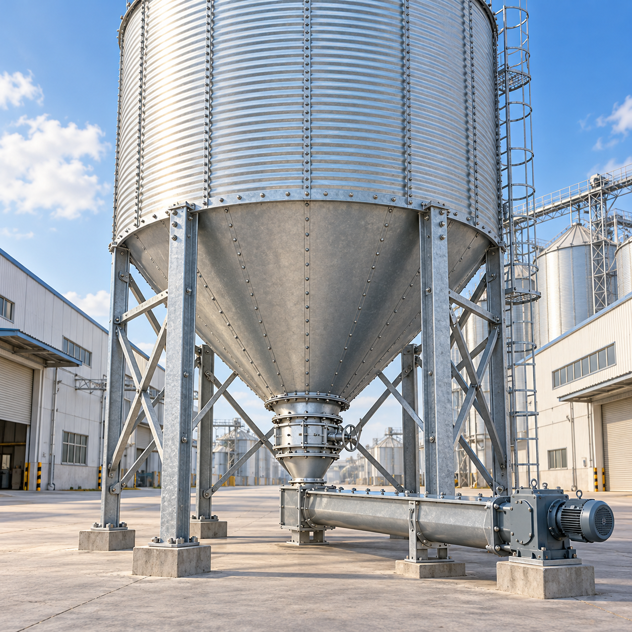
A grain silo can meet its specified storage capacity and still disappoint at discharge. The conveyor runs intermittently, grain remains against the hopper wall, or operators discover that an outlet selected for dry wheat struggles with a wetter batch containing more fines. These problems often begin with a purchasing decision that treats hopper geometry as a standard accessory rather than a material-handling design.
Selecting angles and outlets for Hopper Bottom Grain Silos means balancing flow behavior, structural loading, available headroom, and downstream equipment. For technical evaluators, the useful question is not simply “Which hopper is steeper?” It is “Which combination will discharge the specified grain reliably under the operating conditions we can reasonably expect?”
Define the grain and operating envelope before comparing drawings
A supplier cannot meaningfully select a hopper from grain name and storage tonnage alone. Wheat, maize, barley, and paddy rice differ in particle shape and surface characteristics, while different batches of the same grain may behave differently after drying, handling, or storage.
The design basis should describe both normal conditions and credible difficult conditions:
- Material characteristics: grain type, bulk-density range, particle size, fines, broken kernels, and foreign material.
- Moisture and temperature: receiving limits, expected variation, and potential condensation or moisture migration.
- Storage duration: frequent turnover versus extended residence with consolidation under load.
- Discharge duty: required throughput, operating hours, start-stop frequency, and whether discharge must restart under a full silo.
- Quality requirements: acceptable residual material, segregation limits, and cleanout between grain types.
Do not define the moisture limit only by the average incoming batch. A small wet region or a concentration of fines can become the local restriction that controls discharge. Hopper design also cannot compensate for grain deterioration caused by inadequate drying, aeration, or storage management.
Hopper angle: establish the reference before discussing degrees
Angle notation is a surprisingly common source of procurement errors. One drawing may measure the hopper wall from horizontal; another may use the angle from vertical. A wall at 60° to horizontal is at 30° to vertical. Comparing the numbers without checking the reference reverses the apparent meaning.
Specify the angle reference explicitly on every quotation and approved drawing. In this article, hopper angles are measured from horizontal, so a larger angle means a steeper wall.
Commercial options such as 45° and 60° are useful starting points for layout comparisons, not universal prescriptions for particular grains. A steeper wall generally encourages movement along its surface, but the angle needed for a particular flow pattern depends on wall friction, material properties, and hopper shape.
Angle of repose does not establish the required hopper angle
The angle of repose describes the slope of a free-standing pile. It does not measure how consolidated grain slides against steel under silo pressures. Selecting a hopper angle merely by adding a margin to the angle of repose can therefore produce an unreliable result.
Wall-friction testing uses the grain against a representative contact surface. That surface matters: galvanized sheet, painted steel, stainless steel, and a worn or corroded finish need not provide the same friction. Seams, bolt heads, and abrupt transitions can also interrupt movement even when the nominal wall angle appears adequate.
Separate mass flow from “the silo empties”
In mass flow, all stored material moves when discharge occurs. In funnel flow, a moving channel develops above the outlet while material elsewhere remains stationary until later—or remains trapped. Either pattern may discharge grain, but they have different consequences for residence time, segregation, and cleanout.
Where consistent turnover and minimal stagnant material are important, ask whether the hopper is designed for mass flow and what evidence supports that claim. A steep-looking cone is not proof. Wall angle, wall friction, outlet geometry, and withdrawal across the outlet must work together.
Outlet selection has two separate jobs
The outlet must be large enough to resist flow obstruction and capable of supplying the required discharge rate. These are related requirements, but they are not interchangeable.
Preventing bridging and stable flow channels
Large particles and foreign objects can form a mechanical obstruction. Grain with elevated fines, moisture, or consolidation may develop cohesive strength and form an arch above the opening. In funnel-flow conditions, a stable channel can also leave material around it—a condition commonly called ratholing.
No single outlet diameter reliably covers every grain and condition. For difficult duties, bulk-solids testing should establish the material’s flow function, wall friction, and behavior after relevant storage periods. The results support the selection of hopper geometry and critical outlet dimensions.
For circular outlets, diameter is the key opening dimension. For slots, width is particularly important, but slot length and the withdrawal arrangement also influence performance. Equal opening areas do not mean equal resistance to arching.
Delivering throughput without overwhelming the next machine
A larger opening may improve discharge potential, yet the receiving screw conveyor, belt conveyor, bucket elevator, or process line still sets the usable system capacity. An unrestricted outlet can flood a conveyor inlet even when that conveyor’s nominal rated capacity appears adequate.
Confirm whether the equipment below the hopper is a feeder that controls withdrawal or a conveyor intended mainly to transport an already regulated stream. The distinction affects inlet design, drive torque, and starting behavior under material head.
A slide gate is often best treated as an isolation device. If it will also regulate flow, assess the actual opening shape at partial travel and the resulting flow pattern. A large nominal outlet narrowed by a partly closed gate may recreate the restriction the larger opening was intended to avoid.
Check the height penalty before choosing the steeper cone
Steeper hoppers consume more vertical space. For an ideal concentric conical frustum, the geometric hopper depth is:
h = (D − d) × tan(α) / 2
Here, D is the upper hopper diameter, d is the outlet diameter, and α is the wall angle from horizontal. Use consistent units. This calculation excludes the gate, supporting steel, discharge transition, conveyor, and maintenance clearance.
For illustration, a 6 m upper diameter and 0.4 m outlet produce an ideal hopper depth of approximately 2.8 m at 45° and 4.85 m at 60°. That difference can materially change the support elevation or overall silo height. These figures illustrate geometry only; they do not establish a suitable angle or outlet for a particular grain.
On a height-constrained site, evaluate the complete arrangement rather than flattening the hopper immediately. Options may include changing silo diameter, redistributing capacity among units, or revising the conveying route. Wedge-shaped or other alternative hoppers require their own flow and structural evaluation; they are not interchangeable with cones.
Structural design must follow the selected discharge arrangement
Hopper angle and outlet location influence how grain loads reach the shell, transition ring, supports, anchors, and foundations. Structural assessment must include filling and discharge conditions, not only the static weight of stored grain.
Eccentric outlets and uneven withdrawal can produce asymmetric loading. Multiple outlets may improve process flexibility, but operating one while others remain closed can create load cases that require explicit checking. The operating sequence should therefore be part of the design basis, not left to commissioning.
Ask the structural designer to identify the applicable silo-loading and steel-design standards for the destination jurisdiction. Depending on the project, these may include EN 1991-4 for silo actions and EN 1993-4-1 for steel silos, alongside relevant wind, seismic, foundation, and local regulatory requirements. A material grade or fabrication certificate alone does not demonstrate compliance of the complete silo.
For prefabricated export systems, review material traceability, welding procedures, inspection records, bolt specifications, corrosion protection, and erection tolerances. Transport segmentation and site assembly details should preserve the intended internal profile without creating ledges at joints.
Coordinate the surrounding building without confusing load categories
Where silos discharge into an enclosed handling building, the hopper, conveyor supports, access platforms, and building frame need a coordinated model. A related Multi-Storey Warehouse & Vertical Storage solution can accommodate adjacent bagged-grain storage, racking, or vertical logistics within a constrained site. Its rack-aligned framing and integrated transport routes can inform the surrounding layout, but warehouse floor ratings must not be treated as approval for silo support loads. Concentrated reactions, vibration, and maintenance loads require project-specific verification.
When testing is worth more than another quotation
For clean, dry grain with well-established operating history, documented experience with comparable silo geometry may support selection. Even then, confirm that the comparison includes the same contact surface, moisture range, outlet arrangement, and storage duration.
Testing becomes more valuable when grain contains substantial fines, moisture varies widely, storage is prolonged, or reliable restart is essential. It is also justified when a supplier proposes unusually shallow walls or a compact outlet to meet a tight building envelope.
Request representative samples, including the difficult end of the agreed operating range. A bulk-solids specialist should define the test program and interpret it for the proposed hopper geometry. The objective is a documented design basis—not simply a laboratory report attached to an otherwise unchanged standard drawing.
Avoid relying on vibration as a universal remedy. Depending on the material and installation, vibration can compact material, introduce fatigue loads, or fail to address the underlying restriction. Any flow aid should be selected with structural, grain-quality, and combustible-dust considerations in view.
Specify acceptance evidence, not just dimensions
A useful request for quotation for Hopper Bottom Grain Silos should make competing proposals comparable. Include:
- Grain properties, moisture limits, fines allowance, storage duration, and bulk-density range.
- Required flow behavior, residual-material expectations, throughput, and restart conditions.
- Hopper angle reference, internal finish, outlet shape, and minimum clear dimensions.
- Gate and feeder responsibilities, control interfaces, and permitted operating sequences.
- Overall height limits, equipment clearances, support reactions, and applicable design standards.
- Required calculations, material records, inspection documentation, and commissioning checks.
Agree on how discharge performance will be demonstrated using material within the specified envelope. Observe restart after a representative dwell period, stable delivery to downstream equipment, and residual material after normal discharge. Cleanout inspections must follow confined-space, isolation, and grain-engulfment safety procedures; entering a silo is not an acceptable way to troubleshoot a blockage.
The strongest selection is rarely the steepest hopper or the largest outlet in isolation. It is the combination whose flow assumptions are documented, whose structural consequences are checked, and whose discharge equipment can accept and control the resulting stream. That is what turns a capacity figure on a quotation into dependable daily operation.
We are more than happy to serve you here. If you have any question, please feel free to contact us.