
News center
Related Posts
- ▶ Prefab vs. Conventional Warehouse Construction: Comparing Timelines
- ▶ Planning a Prefab Warehouse: Clear Span, Height and Loading Bays
- ▶ How Long Does It Take to Build a Commercial Steel Building?
Online Message
How Hopper Bottom Grain Silos Feed Batch Processes in Feed Mills
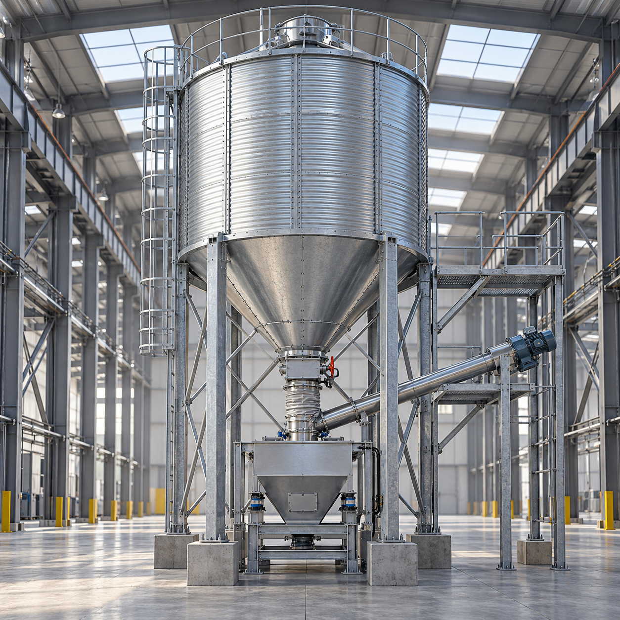
Consistent feed batches begin with controlled ingredient delivery—not simply adequate storage. Hopper Bottom Grain Silos connect bulk grain storage with weighing and mixing systems, using sloped hoppers and controlled discharge equipment to supply material between batch cycles. For feed mill planners, the key questions are how hopper geometry affects grain flow, how feeders coordinate with weighing controls, and how steel supports accommodate storage and operating loads. Understanding these connections helps explain where hopper-bottom silos fit in a batching line and what design factors deserve attention before specifying a system.
Where the silo sits in the process matters
A hopper-bottom silo holds bulk material above a sloping outlet, allowing gravity to move grain toward discharge equipment. Unlike a flat-bottom arrangement that may need sweeping equipment for final unloading, a properly designed hopper can reduce residual material and simplify emptying. It does not, however, guarantee complete discharge or accurate dosing by itself.
In a feed mill, the silo may supply a conveyor and hammer mill, with ground material subsequently entering ingredient bins. In another layout, grain is weighed before grinding. Some hopper-bottom units serve as short-term buffer bins rather than long-term storage. These arrangements place different demands on outlet capacity, controls, access and supporting steelwork.
The distinction is important: a bulk silo does not necessarily feed the mixer directly. Its job may be to keep downstream process bins replenished while weighing and mixing proceed independently. Without that separation, a delayed grain transfer can become a delayed batch.
Gravity starts the flow; hopper design determines whether it continues
Grain does not behave like water. Kernel shape, moisture, fines, consolidation and wall friction all affect movement. A cone that empties dry, clean grain satisfactorily may behave differently after fines accumulate or moisture conditions change. Ground meals and fibrous ingredients can require substantially different handling arrangements from whole grain.
Two flow patterns help explain the difference. In mass flow, material moves throughout the vessel when discharge occurs. In funnel flow, a central channel moves while material near the walls may remain stationary. Funnel flow is not automatically unacceptable, but stagnant zones can complicate stock rotation, cleanout and ingredient consistency.
A steep hopper alone does not establish mass flow. Wall finish, hopper geometry, outlet dimensions and material properties must work together. For difficult ingredients, representative flow-property testing is more useful than selecting a familiar cone angle from a catalogue. Any specified angle should also state whether it is measured from horizontal or vertical.
The feeder interface deserves equal attention. If a feeder draws from only part of an elongated opening, it can create uneven withdrawal despite an otherwise suitable hopper. Enlarging the outlet or adding vibration without checking the underlying flow problem may introduce new structural or operating issues.
How discharge becomes a weighed batch
The silo outlet, isolation device, feeder and weighing system perform different functions. An isolation gate shuts off the stored material for maintenance or process control. A screw, belt or other suitable feeder regulates delivery. The weigh hopper measures the quantity received. Treating a basic slide gate as a precision dosing device often creates avoidable variation.
A typical weigh-hopper sequence works as follows:
- The controller confirms the correct ingredient route, available receiving capacity and a ready weighing system.
- The feeder runs at a higher rate to deliver most of the target ingredient weight.
- Delivery slows near the target, allowing finer control of the remaining quantity.
- The feeder stops before the final target to account for material still travelling toward the scale.
- After the weight settles, the controller checks tolerance and permits discharge when the mixer is ready.
That travelling material, often called in-flight material, is easy to underestimate. A long drop or transfer conveyor means grain can continue reaching the scale after the feeder stops. Cut-off compensation must reflect the actual route and operating conditions rather than a single assumed value.
Mechanical installation also affects accuracy. Rigid connections, poorly supported ducts or tight flexible sleeves can transmit forces into a weigh hopper and distort load-cell readings. The weighing assembly needs suitable isolation, correctly supported connections and calibration under realistic operating conditions.
The fastest feeder is not always the right feeder
A feeder must deliver enough material within the available dosing window while remaining controllable near the target weight. Oversizing can make fine dosing difficult; undersizing can leave the mixer waiting. The useful capacity is therefore linked to recipe quantities, ingredient sequencing and batch timing—not just the mill’s average hourly output.
Buffer capacity can absorb interruptions, but it cannot correct a transfer system that consistently delivers less than production consumes. Planners should check both sustained replenishment capacity and the short-duration demand created by individual batches.
Steel supports must follow the equipment loads
Elevating a hopper creates useful gravity head and space for discharge machinery, but it also concentrates substantial loads into legs, support rings, beams and foundations. The structural design must include stored material, vessel self-weight, attached equipment and maintenance loads, together with applicable wind, seismic and operating effects.
Stored volume is not enough to establish those loads. Design bulk density, filling arrangements and discharge behaviour affect the loading assumptions. Eccentric withdrawal and uneven flow can create conditions that differ from a simple, uniformly loaded vessel. The silo supplier and structural engineer need an agreed loading basis and defined support reactions.
A common coordination mistake is to treat the silo as ordinary equipment placed on a warehouse floor. A floor’s distributed load rating does not establish its capacity beneath concentrated silo supports. Base plates, anchors, concrete foundations, settlement and load transfer all require specific checks.
The building interface needs similar discipline. Roof framing should not receive conveyor, duct or platform loads unless designed for them. Where silos have independent foundations, connections to the process building must accommodate the relative movements identified by the designers. Bracing must remain clear of feeder removal routes and inspection access.
Plan the building around material movement
For a prefabricated steel feed-mill building, the process elevation should be developed alongside the structural grid. Hopper depth, feeder height, weighing equipment and maintenance clearance determine the space required below storage. Selecting the building height first can force awkward transfer routes or leave insufficient room to replace equipment.
A useful parallel appears in the Steel Logistics & Distribution Center approach: the frame is arranged around movement rather than storage volume alone. Its configurable 24–48 m clear spans and 8, 9 or 10 m bays illustrate layout flexibility, not prescribed dimensions for a feed mill. Here, equipment geometry and process loads—not pallet modules—must determine the final grid.
For the China-based prefabricated steel manufacturer described here, a 120,000 m² plant, stated annual output of 100,000 tonnes and deliveries to more than 20 countries provide fabrication and export context. They do not replace project engineering. Material traceability, weld inspection, Tekla coordination models and erection documentation are more directly relevant to resolving silo-support interfaces before shipment.
Likewise, ISO 9001 certification and stated CE, AS/NZS or ASTM credentials should be checked against their actual scope and the destination’s requirements. A quality-management certificate, material standard and structural design approval address different questions.
Cleanout, dust and maintenance affect batch reliability
A silo can discharge adequately and still retain grain on ledges, around transitions or inside poorly detailed connections. Those residues matter when ingredients change or stored material deteriorates. Inspection access, cleanable transitions and a defined emptying procedure should be considered before fabrication, not added after commissioning.
Outdoor steel storage also needs attention to water entry and condensation. Hopper geometry alone does not manage grain condition. Storage duration, incoming moisture, ventilation or aeration provisions, and monitoring requirements should be assessed for the material and climate.
Grain dust can present a combustible-dust hazard. Transfers, enclosed conveyors and dust collection need a site-specific assessment covering ignition control and any required explosion protection or isolation. Applicable measures depend on local requirements and system configuration; neither a steel enclosure nor a dust extractor alone establishes safety.
Maintenance access is equally practical. Operators need safe access to gates, feeder drives, sensors and inspection points. Blockages should never depend on someone entering the silo or striking its walls to restore flow. Isolation, confined-space controls and approved blockage-clearing procedures belong in the operating plan.
Define the interfaces before choosing silo capacity
An initial specification should identify the ingredients, expected bulk-density range, moisture conditions, usable storage requirement and required discharge rate. Alongside those details, record batch sizes, dosing tolerances, transfer distances and the time available to replenish downstream bins.
The next step is a coordinated process drawing showing where material is stored, metered, weighed and mixed. Assign responsibility for hopper flow design, feeder selection, control logic, support reactions, foundations and dust protection. These interfaces are where otherwise competent equipment packages can fail to work together.
Hopper Bottom Grain Silos support repeatable batching when discharge is predictable, dosing is controllable and the structure accommodates the actual equipment arrangement. Before approving a system, trace one ingredient from storage to the mixer—including what happens when flow stops, the scale overshoots or a feeder needs removal. That exercise reveals more than storage capacity alone.
We are more than happy to serve you here. If you have any question, please feel free to contact us.