
News center
Related Posts
Online Message
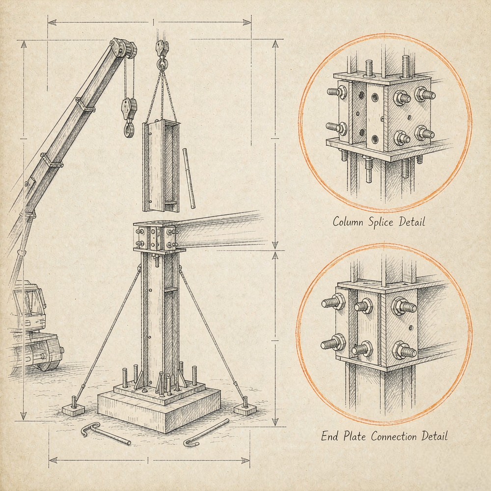
Heavy Steel Structure Erection Connection Safety
How connection design affects heavy steel structure erection safety
Connection design determines whether a heavy steel frame behaves as assumed during erection or becomes vulnerable before the building is complete. A member may have adequate final-stage strength, yet the partially erected structure can still be unstable if its connections cannot develop the required temporary restraint, tolerate expected fit-up variation, or support the planned lifting and sequencing method.
This distinction is central to erection safety. The critical condition is often not the completed structure under design gravity, wind, or seismic loads. It is the intermediate condition: columns standing before permanent bracing is installed, beams landed with only a subset of bolts inserted, a long truss supported at temporary points, or a splice carrying construction loads before field welding is complete. Connection design must address those states explicitly rather than treating them as a site-management issue alone.
Connections control the real load path during erection
In a completed Heavy Steel Structure, force transfer follows the intended structural model: beams frame into columns, bracing stabilizes bays, diaphragms distribute lateral actions, and foundations restrain the frame. During erection, that model is incomplete. Some braces may not yet be installed, roof or floor diaphragms may not be active, and the structure may rely on bolted joints that are only partially tightened.
Connection details therefore establish the temporary load path. They determine how vertical reactions, horizontal forces, torsion, construction loads, and accidental local effects move from one erected element to another. A connection that is satisfactory for final gravity loading may be inadequate for erection if it has insufficient rotational restraint, lacks resistance to temporary lateral force, or depends on components that will be installed later.
A column splice illustrates the issue. In the final condition, the splice may transfer axial force and moment through a designed combination of flange plates, web plates, welds, or high-strength bolts. During erection, however, it must also allow the upper column section to be landed, aligned, held against out-of-plumb movement, and connected without creating an unstable cantilever. The arrangement of erection bolts, plate geometry, bolt-hole type, and available adjustment space directly affects whether the crew can establish a stable condition before releasing the crane.
For safety planning, “connection complete” should not mean simply that some bolts are present. It should mean that the connection has reached the defined condition required to safely transfer the applicable erection-stage actions.
Fit-up is a safety variable, not merely a fabrication quality issue
Poor fit-up is often treated as a productivity problem because it causes delays, slotting requests, reaming, shimming, or field modification. Its safety consequences are more serious. When holes do not align, erectors may be tempted to force members into position, use drift pins beyond their intended alignment function, leave bolts partially engaged, or release lifting equipment before the connection achieves its designed capacity. Connection geometry affects fit-up through several interacting factors:
A detail can be theoretically manufacturable while providing too little field tolerance for the actual erection method. This is especially relevant at interfaces between separately fabricated packages, at long-span roof systems, and at connections where several members converge. A tight node containing braces, beams, handrail supports, service brackets, and architectural plates can leave little room for tools or alignment movement. The result may be a connection that cannot be safely completed in the sequence assumed by the design team.
Good connection design distinguishes between controlled adjustment and uncontrolled field correction. Purpose-designed shims, leveling nuts, pack plates, and approved slotted holes have a defined structural function. Cutting plates, enlarging holes without engineering approval, heating members for alignment, or adding unauthorized welds changes the connection’s behavior and can compromise fatigue performance, slip resistance, fracture toughness assumptions, corrosion protection, or fire protection interfaces.
Bolted joints: bolt count alone does not define safe erection capacity
Bolted connections are widely used because they permit rapid assembly, inspection, and controlled installation. Their erection performance depends on more than nominal bolt strength. The designer must identify whether the joint is intended as a bearing-type connection, a slip-critical connection, or a connection with a specific pretension requirement under the governing standard.
In bearing-type joints, load transfer can occur through bolt bearing against the hole after initial movement. In slip-critical joints, the clamped faying surfaces and bolt pretension are intended to resist slip at the specified load level. The distinction matters where movement would be unacceptable, such as bracing connections, fatigue-sensitive details, structures subject to vibration, or joints with oversized or slotted holes. It also matters during erection when temporary lateral movement could affect frame alignment or destabilize a partially completed bay.
Installation requirements should be tied to the design intent. In US practice this commonly involves the applicable provisions of the RCSC Specification and the project’s structural steel requirements; in European project frameworks, EN 1993-1-8 addresses joint design while EN 1090-2 sets execution requirements for steel structures. These documents should not be mixed selectively. The governing contract documents must establish the applicable standard system, bolt assembly requirements, inspection method, and acceptance criteria. Several field checks deserve particular attention:
Access is also a design issue. If a wrench cannot reach the nut, if a bolt must be installed from an unsafe position, or if final tightening is blocked after adjacent steel is erected, the detail has not fully accounted for erection. Three-dimensional clash review is useful, but it should be supplemented by a practical review of tool clearance, worker access, bolt insertion direction, and the sequence in which adjacent components close off the connection.
Welded field connections require a different risk model
Field welding can provide continuity where bolting is impractical or where the structural system requires a rigid moment connection. It also introduces variables that are less predictable than shop welding: weather exposure, access constraints, variable fit-up gaps, welding position, site power conditions, and the need to protect the joint from contamination.
A field-welded splice should not be assumed to provide its final capacity until the specified weld sequence, inspection, and any required non-destructive examination have been completed and accepted. If the erection plan relies on the connection before that point, temporary bolting or temporary bracing must carry the relevant loads.
Weld sequence is particularly important in heavy sections. Unbalanced welding can pull a member out of line, induce residual stress, or lock in distortion that later affects adjacent fit-up. The detail should make clear which welds are completed in the shop, which are completed in the field, whether backing or run-off tabs are required, and how access is maintained for welding and inspection. Where a project follows a defined welding standard, the welding procedure specification, welder qualification, joint preparation, preheat controls where applicable, and inspection requirements need to be aligned with the project documents. Comparable controls are required under other governing execution standards.
Surface protection creates another interface risk. Galvanized, painted, or metallized components may require defined treatment at field-weld locations. Burning through coatings without a repair procedure can leave exposed areas with reduced corrosion resistance. Conversely, coating left within a weld zone can create weld-quality concerns. These details should be resolved before fabrication rather than managed through site improvisation.
Splices and moment connections deserve early erection-stage review
Heavy steelwork frequently uses splices to match transport limits, shop handling capacity, and erection crane capacity. A splice is not just a shipping break. Its location changes member handling, temporary stability, and the installation sequence.
For a beam or girder splice, the field joint may need to resist self-weight from an overhanging segment while the opposite side is still supported by a crane. For a column splice, the lower column and its base connection must resist temporary actions from the newly landed upper segment. For a truss splice, the geometry of the splice can affect whether the truss is assembled on the ground, lifted as a module, or erected piece by piece.
Moment connections introduce a further concern: their stiffness can attract forces before the rest of the lateral system is active. A nominally rigid connection may restrain rotation in a way that transfers temporary forces into columns, foundations, or incomplete bracing systems. The erection analysis should identify whether joints are treated as pinned, partially restrained, or moment-resisting at each stage, rather than assuming the final analytical model applies from the first lift.
In architecturally exposed steel, connection decisions become more constrained because visible plates, concealed fasteners, curved members, and narrow profiles can reduce adjustment space. A public crossing such as a Steel Structure Landscape Bridge may require coordinated review of segment joints, lifting points, curved geometry, and visible surface transitions. Concealing a joint does not remove its erection requirements; it can make inspection access and tolerance management more demanding.
Temporary stability must be designed into the connection strategy
The primary structural engineer establishes the permanent load-resisting system, but erection safety depends on a coordinated temporary works approach. The erector’s means and methods remain distinct from design responsibility, yet safe execution requires the design documents, connection details, and erection plan to be compatible.
Critical questions include whether columns can stand safely before permanent bracing is connected, whether beam-to-column joints provide sufficient restraint during bay completion, where temporary guys or braces can be attached, and whether those attachment points have been designed for the resulting forces. Improvised attachment to a thin plate, handrail lug, secondary member, or unverified flange can introduce local damage or failure.
Wind deserves particular attention because exposed steel members can experience significant lateral action long before cladding, floors, or diaphragms are in place. A frame that appears stable under calm conditions may not meet the required erection-stage stability criteria under the site wind limits defined in the erection plan. Connection design must support the temporary bracing layout, not conflict with it by occupying the only practical attachment locations or preventing installation in the required sequence.
Inspection should verify the intended connection state
Connection inspection is most effective when it follows the progression of erection rather than occurring only after a large area has been assembled. The key question is not merely whether the completed joint looks correct, but whether each joint was safe at the stage when it carried construction loads.
A useful inspection record links member identification, connection type, bolt installation status, final tightening status where required, weld completion, inspection hold points, approved shims or pack plates, and any engineering disposition for nonconformance. This creates traceability when work proceeds across multiple shifts or when a partially erected zone is exposed to weather before final completion.
Nonconformances should be classified by structural consequence. A minor coating blemish and a misaligned moment-connection bolt group are not equivalent. The latter can alter force transfer, reduce edge distance, interfere with bolt installation, or indicate broader dimensional error. The response should be an engineered disposition based on the governing design and execution requirements, not a field decision driven solely by schedule pressure.
The safest heavy steel erection is not created by adding more steel to every joint. It comes from making the connection’s function clear at every stage: how the member is landed, what holds it before final completion, how forces are transferred, what tolerance is available, how bolts or welds are verified, and which temporary restraints remain necessary. When those conditions are resolved in detailing and controlled in the field, connection design becomes an active barrier against instability rather than a late-stage source of correction work.
We are more than happy to serve you here. If you have any question, please feel free to contact us.